


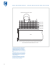
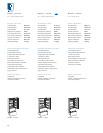
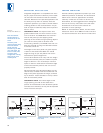

PLANNING INFORMATION
Before moving the Integrated unit into place, be
sure that the finished opening dimensions, elec-
trical and plumbing locations and minimum door
and drawer clearances are accurate. Refer to the
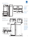
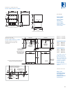
Installation Specifications illustration for your
model on the following pages. Be sure your
installer has this information before finishing
work is completed.
Integrated models without an automatic ice
maker will not require the plumbing connections
shown in the illustrations.
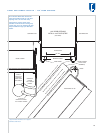
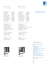
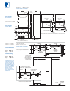
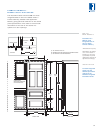
The height of the tall unit is set at 2032 mm.
You can allow the top of the door panel to
exceed this dimension with caution. If you are
working with 2134 mm or 2438 mm neighboring
panels, you can utilize door panels to match this
height. Other critical dimensions regarding the
door swing, drawer openings and toe kick clear-
ance are noted in the Overall Dimensions illustra-
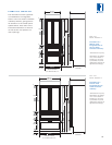
tions on the following pages. Also refer to the
full-scale illustrations at the end of this section
for specifics on door openings and other specifi-
cations.
IMPORTANT NOTE: The anti-tip bracket must be
installed to prevent the unit from tipping
forward.
ELECTRICAL REQUIREMENTS
International models from the factory designed
without a transformer require a 220/240 V AC,
50/60 Hz electrical supply, fused at the correct
rating for the unit. If required by local or national
codes, the power cord can be easily replaced
using the power inlet device.
International models using a factory installed
transformer require a 220/240 V AC, 50/60 Hz
electrical supply, fused at the correct rating for
the unit. These models will come equipped with
Schuko power cords. The power cord may need
to be replaced depending on local and national
codes. The USA power cord that is supplied
with the product must be disconnected with the
appropriate transformer output to be connected
in its place.
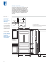
IMPORTANT NOTE: The electrical outlet must
be grounded. The outlet must be flush with the
back wall. Refer to the Installation Specifications
illustration for your model for exact placement.
IMPORTANT NOTE: A ground fault circuit
interrupter (GFCI) is not recommended and may
cause interruption of operation.
32
Do not use an extension cord or 2-prong
adapter. Electrical ground is required.
Do not under any circumstances remove
the power supply cord ground prong.
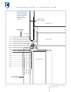
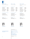
PLUMBING CONSIDERATIONS
For models with an automatic ice maker, rough
in the water supply line. Connect a 6.35 mm OD
copper line to the house supply, being sure to
use an easily accessible shut-off valve between
the supply and the unit. This shut-off valve
should not be installed behind the unit.
Do not use self-piercing valves. A saddle valve
kit (4200880) is available from your Sub-Zero
dealer. An in-line filter is required when water
conditions have a high sediment content. The ice
maker operates on constant water pressure
between 1.4 bar and 6.9 bar.
IMPORTANT NOTE: In some cases, a reverse
osmosis water filter system may not be able to
maintain the minimum pressure consistently.
The Installation Specifications illustration for
your model on the following pages shows the
precise placement of the water line. When
routing the water through the side walls, you
must place the water line within 13 mm of the
floor and as close as possible to the back wall.
The line must be routed around the anti-tip
bracket so it clears the bracket and the leveling
feet of the unit as shown in the top view of the
illustration. Regardless of the routing, allow for
686 mm of excess copper tubing to remain
outside the wall or floor for easy connection to
the unit.
IMPORTANT NOTE: Do not route water supply
line in front of the compressor tray. The tray
must be slid forward for service.
INSTALLATION
Refer to the
installation instruc-
tions shipped with
each Sub-Zero
product for detailed
specifications.