


7
ENGLISH
SECTION 2 - INSTALLATION
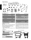
III. ASSEMBLY
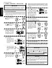
A. Legs/Casters Installation
1. Move the oven to its final location using the casters that are
pre-attached to the bottom panel.
2. Elevate the oven until its bottom surface is at least 18"
(457mm) above the floor.
3. Remove the casters from the bottom of the oven. These
casters are attached for pre-installation movement ONLY,
and may not be left on the oven.
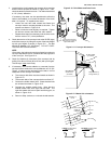
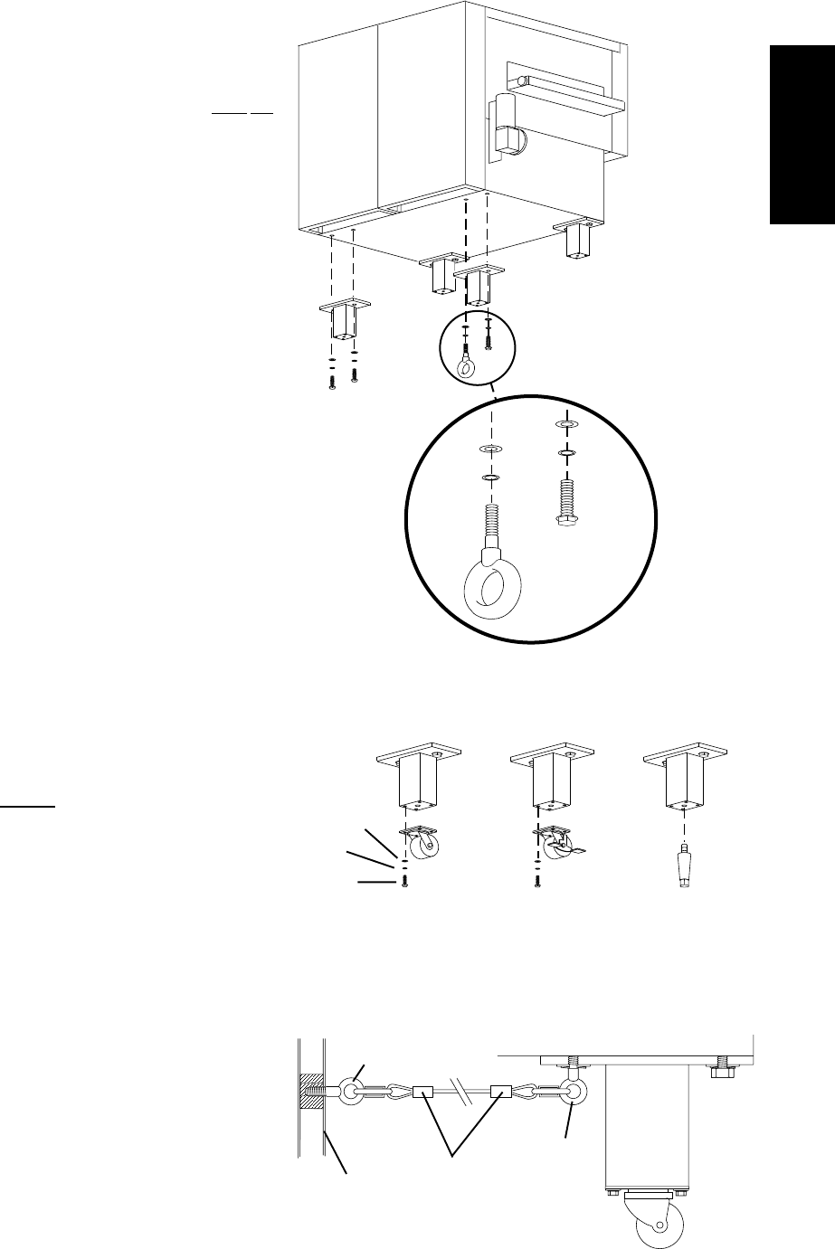
4. Attach one of the 9" (229mm) leg extensions to the REAR
DRIVE-END (rear left) corner of the oven, as shown in
Figure 2-3. On the OUTSIDE hole of the leg extension, use
one 3/4"-10 hex screw, one 3/4" lockwasher, and one 3/4"
flat washer. On the INSIDE hole of the leg extension, use
the 3/4"-10 shoulder eyebolt (supplied in the Installation
Kit) in place of the screw.
5. Attach the 3 remaining leg extensions using the remaining
screws, lockwashers, and flat washers.
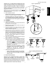
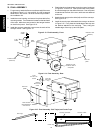
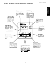
6. Attach EITHER the 6" (152mm) adjustable legs OR the
casters to the bottom of the 9" leg extensions, as follows:
THE 6" (152mm) ADJUSTABLE LEGS may only be
used if there is at least 24" (610mm) service access
on ALL FOUR sides of the oven. To attach the adjustable
legs, screw the threaded stud into the center hole of the
leg extension. See Figure 2-4.
CASTERS may be used in all installations. To attach
the casters, use the 3/8"-16 hex screws, 3/8"
lockwashers, and 3/8" flat washers supplied in the
Installation Kit. See Figure 2-4. The two locking
casters should be installed at the front of the oven.
7. Lower the oven to the floor.
If the 6" (152mm) legs were used in the installation,
adjust the "foot" section of each leg to level the oven.
If the casters were used in the installation, lock the front
casters in place.
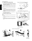
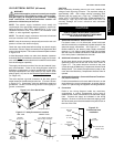
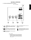
B. Restraint Cable Installation
Because the oven is equipped with casters, a restraint cable
assembly must be installed to limit the movement of the
appliance without depending on the connector and the quick
disconnect device or its associated piping. Anchor one end of
the cable to the eyebolt on the left rear leg extension. Anchor the
opposite end to the wall as shown in Figure 2-5, using the
eyebolt supplied with the restraint cable assembly.
Fig. 2-3 - Leg Extensions
Fig. 2-4 - Adjustable Legs and Casters
Fig. 2-5 - Installing the Restraint Cable
ventilation at all. The best method of supplying return air is
through the heating, ventilation and air conditioning (HVAC)
system. Through the HVAC system, the air can be temperature-
controlled for summer and winter. Return air can also be
brought in directly from outside the building, but detrimental
effects can result from extreme seasonal hot and cold tempera-
tures from the outdoors.
NOTE: Return air from the mechanically driven system
must not
blow at the opening of the baking chamber. Poor oven baking
performance will result.
C. Other ventilation concerns
Special locations, conditions, or problems may require the
services of a ventilation engineer or specialist.
Inadequate ventilation can inhibit oven performance.
It is recommended that the ventilation system and duct
work be checked at prevailing intervals as specified by the
hood manufacturer and/or HVAC engineer or specialist.
Flat
washer
Lock
washer
Hex
screw
Eyebolt (this
leg extension
only)
Rear of oven
Drive end
(left side of
oven)
Adjustable
leg
Flat
washer
Lock
washer
Hex
screw
Caster with brake -
front legs
Caster without
brake - rear legs
OR OR
3/4 (19mm)
eyebolt
Restraint cable
assembly
Eyebolt on
left rear leg
extension
Wall of
structure