


25
Models 345, 346, 349, 355 Operating P rocedures
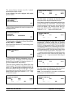
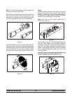
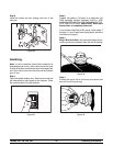
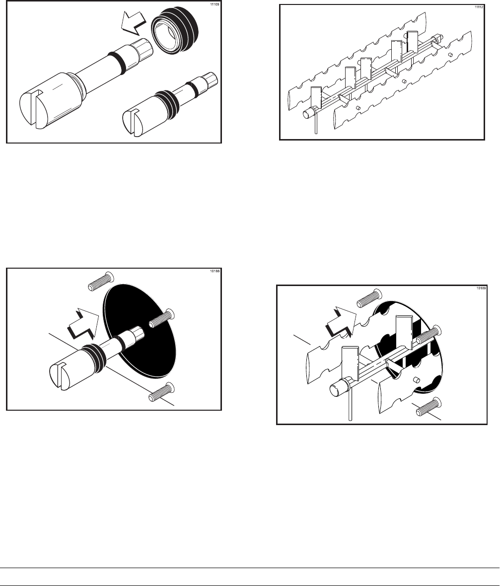
Note: The drive shaft bushing must be positioned in
the center of the drive shaft s eal.
Slide the seal and bushing ov er the shaft and groove
until it snaps into place. Fill the inside portion of the
seal with 1/4” more lubricant and evenly lubricate the
end of the seal that fits onto the rear shell bearing.
Figure 11
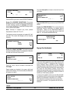
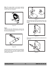
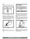
Insert the beater drive shaft into the freezing cylinder,
hex end first, and into the rear shell bearing until the
seal fits securely over therear shell bearing. Becertain
the drive shaft fits into the drive coupling without
binding. Remove any excess lubricant from t he seal.
Figure 12
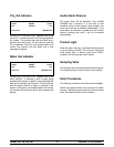
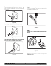
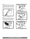
Step 2
Install the beater assembly. First check the scraper
blades for any nic ks or s igns of wear. If any nicks are
present or if the blade is worn, r eplace both blades. If
the blades are in good condition, place the scraper
blades ov er the holding pins on the beater.
Note: Each hole on the scraper blade must fit
securely over eac h pin.
Figure 13
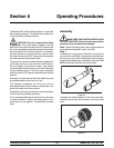
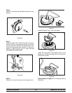
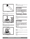
Align the flats on the end of the beater assembly with
the drive shaft. Make sure the beater assembly
locating pin is inposition inthelocating holeof thedrive
shaft. Turn the beater slightly to be certain that the
beater is properly seated. When in position, the beater
will be approximately 3/8” inside the front of the
freezing cylinder.
Important: Failure to properly seat the beater may
cause damage to the beater and the door.
Figure 14