


26
Models 345, 346, 349, 355Operating P rocedures
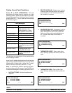
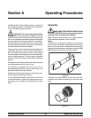
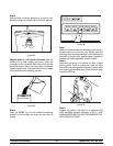
Note: The scraper blades on the beater assembly
should be in the 6 and 12 o’clock positions. This will
enable f reezer door installation.
Figure 15
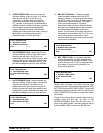
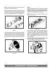
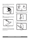
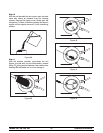
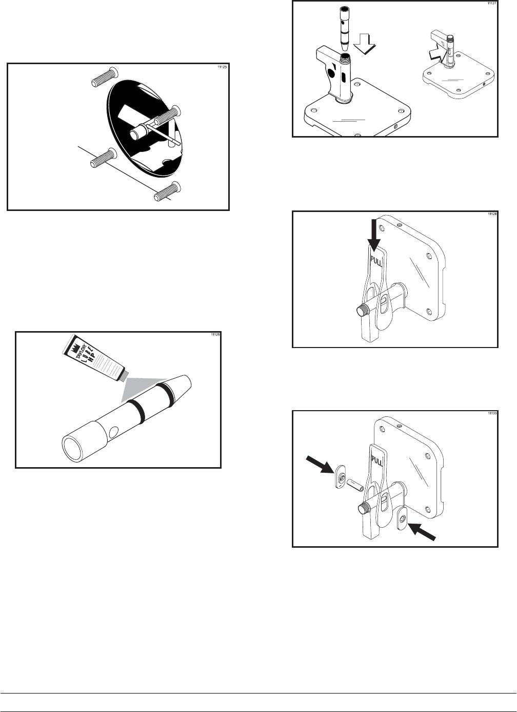
Step 3
Install the draw valve. Slide the two o-rings into the
grooves on the draw valve. Lubricate the o-rings and
the valve as illustrated below.
Figure 16
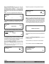
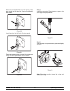
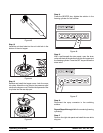
Insert the draw valve into the freezer door spout from
the front of the unit. The valve is properly installed
when the hole in the draw valve is visible in the slot of
the freezer door spout.
Figure 17
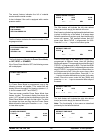
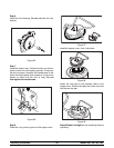
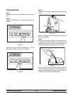
Snap the draw valve handle onto the door spout. Align
the hole in the draw valve with the slot in the draw
handle.
Figure 18
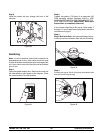
Slide thepivot pin through the draw handle and into the
draw valve.
Figure 19