


Model 500/600
5-4. INFORMATION MODE
DETAILS
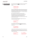
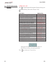
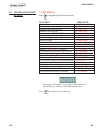
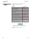
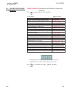
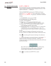
10. INP A_VHDSF_M
This mode displays the status of components and inputs. If the input
signal is detected, an identifying letter is displayed (see below). If the
signal is not detected, “_” is displayed.
W
ith the COOK/PUMP switch turned to COOK, and all inputs
detected, “H_ P_ A_VHDSF_M” shows in the display, for electric
fryers; “H_ P_ A_VHDSFP_” for gas fryers. See below for definition
of codes.
A = COOK/PUMP switch turned to COOK
B = COOK/PUMP switch in PUMP position
V
= Volts - 24 VAC detected
H = High Limit - If “H” is present, the high limit is good;
if “H” is missing, the high limit is tripped (overheated) or faulty
D = Drain switch - If “D” is present, the drain handle is closed;
if “D” is missing, the drain is open or faulty
S = COOK/PUMP switch “on” interlock circuit: If “S” is present, the
COOK/PUMP switch is in the COOK position; if the “S” is
missing, the power switch is either off, failed, or wired incorrectly
F = Fan
P = PV - Detects 24 V jumper to PV terminal - gas fryers only
M = MV - Detects 24 V jumper to MV terminal - electric fryers only
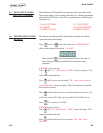
Press to view the specific status of each input. An underscore
(“_”) indicates the input is not presently detected. A checkmark (“
\
/” )
indicates the signal is detecting a normal input. A blinking (“X”)
indicates the signal is presently detected, but is detected as a half-wave
(partially failed) input.
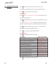
The V, H, D, S, F, P, and M signals below are wired in series.
The first signal missing out of this sequence will generally
cause all signals to the right of it to be missing as well.
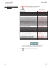
Press to continue onto OUTP H* P_ checks.
303 5-33