


Page 82 of 118 SGB Batch Blender with Mitsubishi Controller
6-6 Electrical
6-6-1 Description and Objectives
This section is designed to give the operator an overview of the electrical
system that controls the SGB blending system. Since the SGB’s control
panel is a self-contained pluggable item, seldom will a maintenance
person be required to enter the control panel. For purposes of
understanding the system, it is advisable that the maintenance personnel
be familiar with not only the internal workings of the control panel, but
also with the input and output signals to the SGB unit.
This section includes the following:
• Internal components of the control panel
• Input signal to the control panel
• Output signals from the control panel
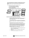
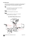
6-6-2 Internal Components of the Control Panel
Note: See Section 12-2 for complete electrical schematics.
This section describes the internal components of the SGB blending
system control panel. It is not the intent of this section to completely
familiarize the reader with the details on industrial control panel
construction or standards, but simply to familiarize the reader with the
major components inside the SGB control panel.
The customer must supply 120/1/50 or 60 (or 220/1/50 or 60) via wires
L1 & L2 (N). Please insure that the earth ground connection is properly
connected to an established earth ground.
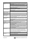
“Power on” is indicated by a lighted on/off switch.
“Slide gate below mixer” switch controls position of optional slide gate.
“Safety Active” light displays status of safety interlock circuit. Audible
alarm horn alerts operator to blender fault.
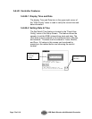
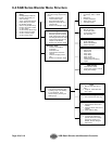
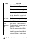
6-6-3 Input Signals to Programmable Controller
The SGB blending system has two main input signals that it uses from
the blending process: the mix hopper high level signal and the weigh
hopper load cells. This, of course, does not include the operator
touchscreen input.
The mix hopper high level signal is generated by a proximity level sensor
located in the right hand portion of the mixer chamber (viewing from the
mixer door).
Load cells require +10 volts DC to operate. This is known as the load
cell’s excitation voltage.