


19
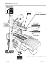
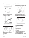
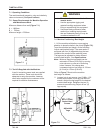
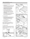
M8 x 1.25mm
Socket Head
Screws
Adjustable
Legs
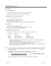
Figure 7-2
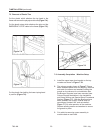
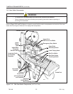
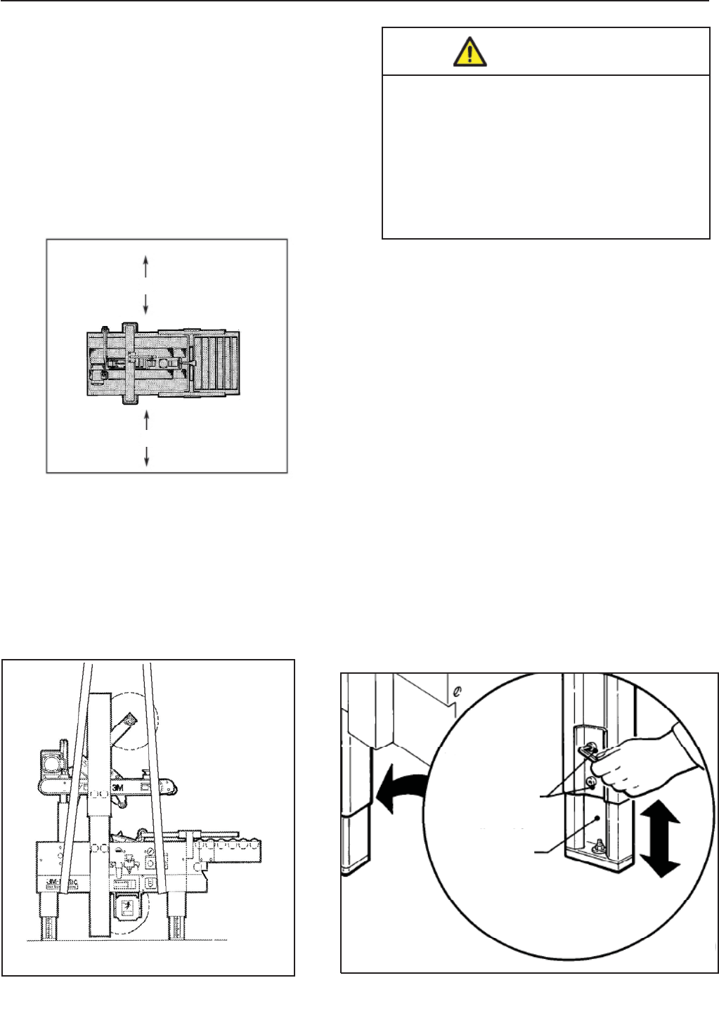
7.4 Machine Positioning / Bed Height
1 - Lift the machine with belts or ropes paying
attention to place the belts in the points (Figure 7-2).
To set the machine bed height, do the following:
7-INSTALLATION
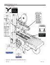
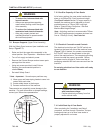
Figure 7-1
A
B
2011 July
700r-NA
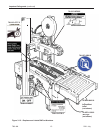
2. Loosen, but do not remove, two (2) M8 x 1.25
socket head screws in one leg (use M6 hex
wrench). Adjust the leg length for the desired
machine bed height. Retighten the two (2)
screws to secure the leg. Adjust all four (4)
legs equally.
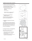
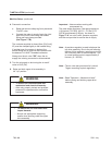
Adjust machine bed height. The case sealer is
equipped with four (4) adjustable legs that are
located at the corners of the machine frame.
The legs can be adjusted to obtain different
machine bed heights - See Specif cations.
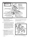
Note – Minimum machine bed height can be
reduced to 570mm [22.5 inch] by moving
outer columns up one set of mounting
holes.
However, this change also
increases minimum
box height of 120 mm
[4.8 inch] to 170mm [6.8 inch].
Refer to Figure 7-3 and set the machine
bed height as follows:
Figure 7-3
A tool kit containing some tools are supplied
with the machine. These tools should be
adequate to setup the machine, however,
other tools supplied by the customer will be
required for machine maintenance.
7.3 Tool Kit Supplied with the Machine
7.1 Operating Conditions
The machine should operate in a dry and relatively
clean environment (See Specif cations).
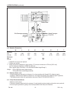
7.2 Space Requirements for Machine Operation
and Maintenance Work
Minimum distance from wall (Figure 7-1):
A = 1000mm.
B = 700mm.
Minimum height = 2700mm.
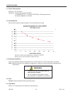
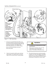
• To reduce the risk associated with
muscle strain:
− Use the appropriate rigging and
material handling equipment when
lifting or repositioning this equipment.
− Use proper body mechanics when
removing or installing taping heads
that are moderately heavy or may be
considered awkward to lift.
WARNING