


21
Machine Setup (continued)
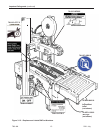
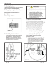
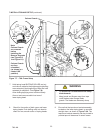
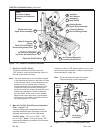
4. Pneumatic connection.
a. Read and remove safety tag from pneumatic
"On/Off" valve.
b. Connect the main air supply line to the inlet
side of the on/off valve using the barbed
fi tting and hose clamp provided
(See Figure 7-7B).
The customer supplied air hose (8mm [5/16 inch]
ID) must be clamped tightly to the barbed fi tting.
If another type of connector is desired, the
barbed fi tting can be removed and replaced with
the desired 1/4-18 NPT threaded connector.
Always turn the air valve "Off" when the air
supply line is being connected or disconnected.
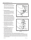
5. Turn the air supply on be turning the air on/off
valve to SUP (On).
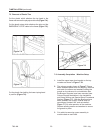
6. Raise and latch upper drive assembly in
full "Up" position.
Note – The air valve has provisions for Lockout/
Tagout according to plant regulations.
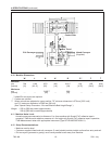
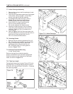
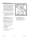
Note – A precision regulator is used to balance the
top drive assembly. Due to the self relieving
feature of this regulator a small amount of air
will continually vent to the atmosphere. This
is normal and amounts to approximately 3
litre/min. [0.1 SCFM].
Important – Use care when working with
compressed air.
The case sealer requires a 5 bar gauge pressure
110 litre/min [70 PSIG], @21°C, 1.01 bar [3.75
SCFM] compressed air supply. As shown in
Figure 7-14, an on/off valve, pressure regulator,
and fi lter are provided to service the air supply.
Note – Read "Operation – Mechanical Latch"
before raising and latching upper drive
assembly.
• To reduce the risk associated with
impact hazards:
− Always use appropriate supporting
means when working under the upper
drive assembly
WARNING
700r-NA
2011 July
• To reduce the risk associated with
mechanical and electrical hazards:
− Allow only properly trained and qualifi ed
personnel to operate and/or service this
equipment
WARNING
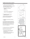
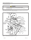
7-INSTALLATION (continued)