


25
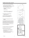
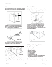
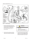
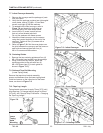
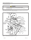
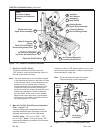
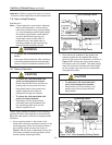
Refer to Figure 7-13 and 7-14 below to acquaint yourself with the various components and controls of the case
sealer. Also see Figures in Manual 2 for taping head components.
• To reduce the risk associated with mechanical and electrical hazards:
− Read, understand and follow all safety and operating instructions before operating or
servicing the case sealer
WARNING
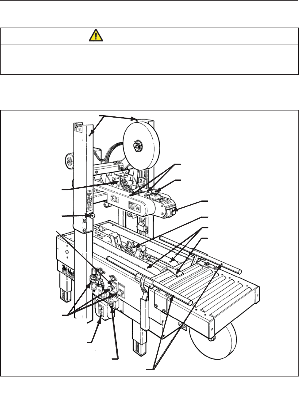
Figure 7-13 – 700r Case Sealer Components (Left Front View)
700r-NA
2011 July
7-INSTALLATION AND SETUP (continued)
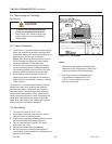
7.15 Case Sealer Components
Upper
Taping
Head
Upper Drive
Assembly
Release Knob
Electrical
On/Off Switch
Box Centering Guides
Infeed End
Centering Guide
Air Pressure
Regulator
Box Side Guides
Centering Switch
Upper Drive
Assembly Switch
Upper Drive
Belt Covers and Belts
Box Drive Belts
Lower Taping Head
Emergency Stop Switch
Column Guards
Pneumatic
Controls
Electrical
Control Box
w/Circuit Breaker
and Contactor