


47
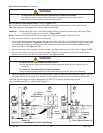
Special Setup Procedure - Column Bumper Installation
Installation Instructions - Column Bumper
(A parts package is included with the unit for installation purposes).
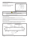
The Column Bumper will be located on the column according to the size of the box that is to be taped
(Refer to Figure 13-10A).
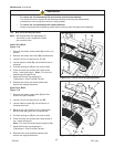
1. Raise and Lock the Upper Drive Assembly. Important: This procedure is for authorized personnel ONLY!
2. Turn off air supply and electric power.
3. Remove Guard (see Installation and Setup / Figure 7-7), the existing holes for
installing Column Bumper should be visible.
4. Remove Column Bumper and set screw parts package from the carton.
5. Position Bumper as needed (the recommended position is shown in Figure 13-10A).
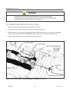
6. After the new Bumper is installed, re-install the Safety Guard (see Installation and Setup Section/Figure 7-7).
7. Turn on air supply and electric power.
* Note - Important: See Figure 15104 for Plate Change. When Column Adjusted to "Raised" Position -
Parts #40 and #41 are removed and replaced by Part #42.
Also: DO NOT Use the Bottom Set of Bumper Holes.
These Holes are Used in Special Applications ONLY!!!
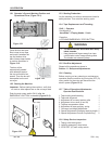
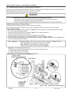
13.11 Special Setup Procedure - Column Bumper Installation
Purpose of Column Bumper Special Setup Procedure: Installing Column Bumpers restrict the operating range of
the upper assembly in proportion to the size of boxes to be sealed.
This installation results in an increase to the operating speed.
• To reduce the risk associated with mechanical and electrical hazards:
− Turn electrical and air supply off and disconnect before performing any adjustments,
maintenance or servicing the machine or taping heads
− Allow only properly trained and qualifi ed personnel to operate and/or service this equipment
WARNING
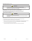
Important: Some bumper positions may:
1) Allow upper and lower taping heads to come into contact with each other.
2) Create added stress to the bumper.
3) Cause a malfunction of the machine.
These events can potentially cause damage to the machine
700r-NA
2011 July
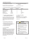
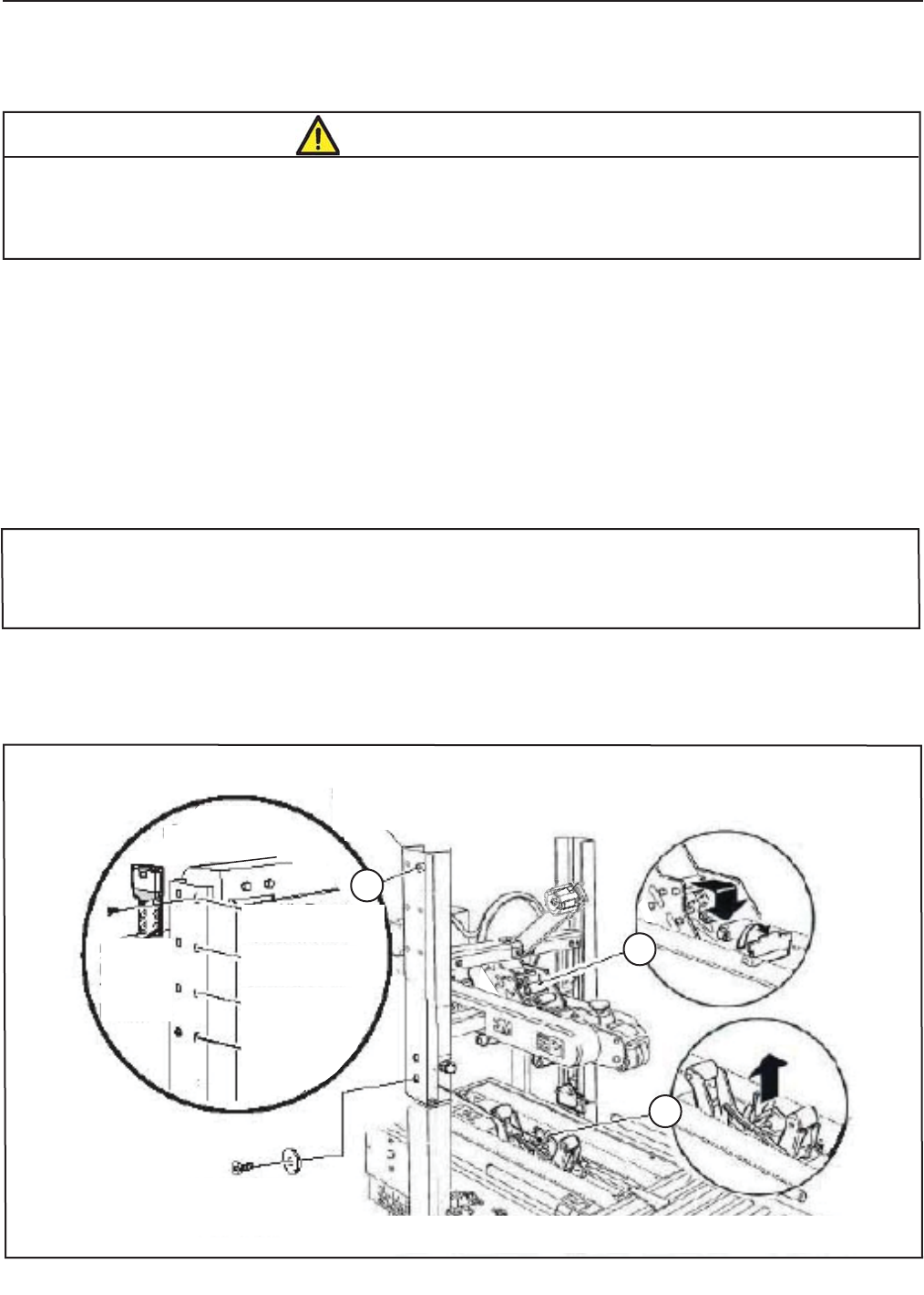
Shown is after-
Safety Guard is Removed
A
B
C
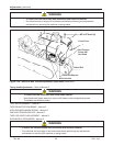
Figure 13-10 – Case Sealer Frame Changes
Safety Guard
Set Screws
& Washers
Safety Guard
Box Ht. Range
4.75"/120mm
Box Ht. Range
8.00"/2000mm
Box Ht. Range
11.25"/285mm
Box Ht.Range
14.50"/
375mm