


29
7.17 Theory of Operation
The air supply powers movement of the centering
guides and upper drive assembly to automatically
adjust the case sealer to the box size being sealed
as follows:
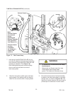
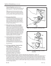
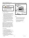
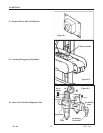
1. A box centering switch in the center of the
infeed roller conveyor actuates movement of the
centering guides. When the operator pushes a
box onto the infeed conveyor, as shown in
Figure 7-19, the lever is depressed causing the
air cylinder powered centering guides to move
inward, thereby centering the box.
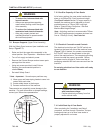
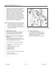
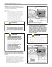
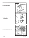
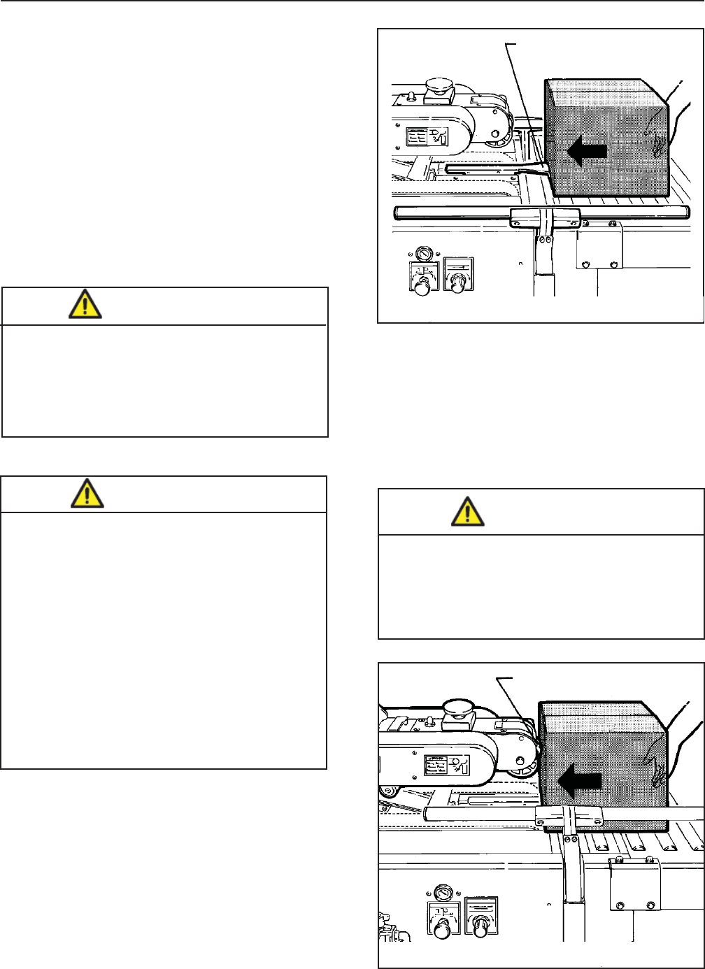
2. Once the box is centered by the guides, the
operator pushes the box against the raising
switch on the upper drive assembly, as shown in
Figure 7-20, causing the upper taping head to
be raised by two air cylinders. The upper taping
head will continue to rise above the box height
so the operator can insert the box underneath
the upper drive belts.
Figure 7-20 – Drive Assembly Raising Switch
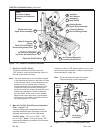
7.16 Tape Loading/Threading
See Manual 2.
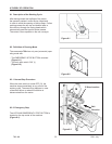
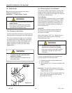
Note – If lower tape drum is mounted in alternate
lower outboard position, remove taping
head from machine bed by pulling straight
up, insert threading needle in taping head
and replace taping head. Install tape roll
on drum (adhesive on tape leg up),
thread tape under knurled roller on
outboard mount, then attach tape to
threading needle and pull tape through
taping head with threading needle.
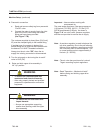
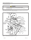
Important – Before turning drive belts on, be sure
no tools or other objects are on the conveyor bed.
• To reduce the risk associated with
pinch and entanglement hazards:
− Always feed boxes into the machine by
pushing only from the end of the box
− Keep hands clear of the upper head
support assembly as boxes are
transported through the machine
• To reduce the risk associated with
pinch and impact hazards:
− Keep away from the pneumatically
controlled upper drive assembly and
box centering guides when air and
electric supplies are on.
CAUTION
• To reduce the risk associated with
pinch and entanglement hazards:
− Keep hands, hair, loose clothing, and
jewelry away from moving belts and
taping heads
CAUTION
Figure 7-19 – Box Centering Switch
Box Centering Switch
Raising Switch
• To reduce the risk associated with muscle
strain:
− Use proper body mechanics when removing
or installing taping heads that are moderately
heavy or may be considered awkward to lift
WARNING
7-INSTALLATION AND Setup (continued)