


23
7-INSTALLATION AND SETUP (continued)
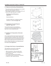
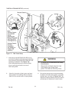
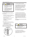
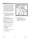
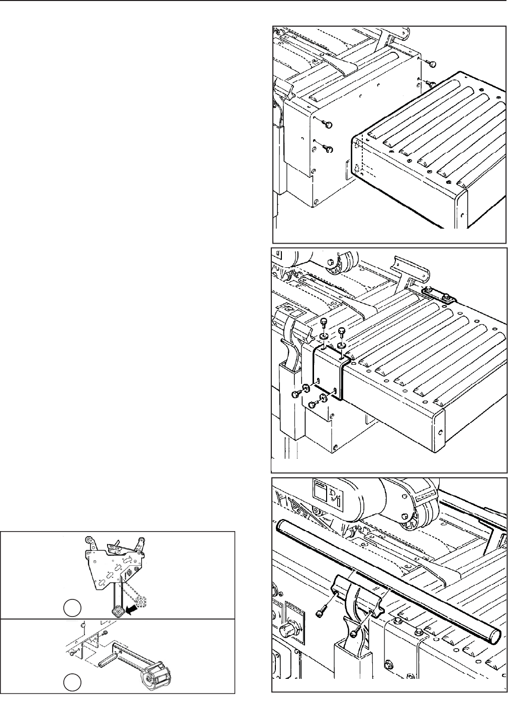
7.8 Centering Guides
1. Remove the two centering guides and four (4)
M6 x 20 socket head screws from the package.
2. Using a 5mm hex key wrench, attach the
centering guides to the rails with four (4)
M6 x 20 screws (two [2] in each guide as
shown in Figure 7-11).
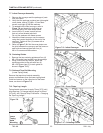
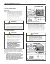
1. Remove the conveyor and the package of parts
from the carton.
2. Verify that the package contains two right angled
cover plates, twelve (12) M8 x 15 hex head
screws, and eight (8) M8 fl at washers.
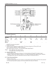
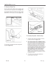
3. To assemble the infeed conveyor, refer to
Figure 7-9 and locate four bolt holes on
the infeed end of the case sealer frame.
4. Insert a M8 x 15 screw in each hole so
that only a few threads take hold.
Do not use washers with these screws.
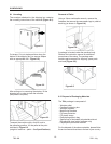
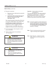
5. Attach the infeed conveyor over the screws
using the inverted keyholes in the end of the
conveyor. Tighten all four (4) screws with a
13mm wrench.
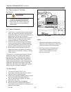
6. Refer to Figure 7-10. Set the cover plates over
the joint between the conveyor and the frame on
each side and secure them with four (4)
M8 x 15 screws and M8 washers.
7.7 Infeed Conveyor Assembly
Figure 7-9 – Infeed Conveyor
Figure 7-10 – Cover Plates
Figure 7-11 – Centering Guides
700r-NA
2011 July
7.10 Tape Leg Length
Taping heads are pre-set to apply 70mm [2.75 inch]
long tape legs. To change tape leg length to 50mm
[2.0 inch], see "Special Setup Procedure – Changing
the Tape Leg Length."
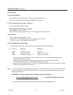
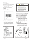
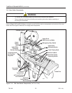
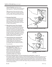
7.9 Outboard Tape Roll Mounting
(Lower Taping Head)
Remove the tape drum bracket assembly,
spacer and fasteners from the lower taping head.
Install and secure on the infeed end of the lower
frame, as shown in Figure 7-8.
A
B
Figure 7-8
Lower
Taping
Head
Mounting