


22
7-INSTALLATION AND SETUP (continued)
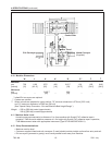
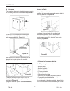
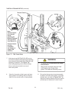
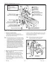
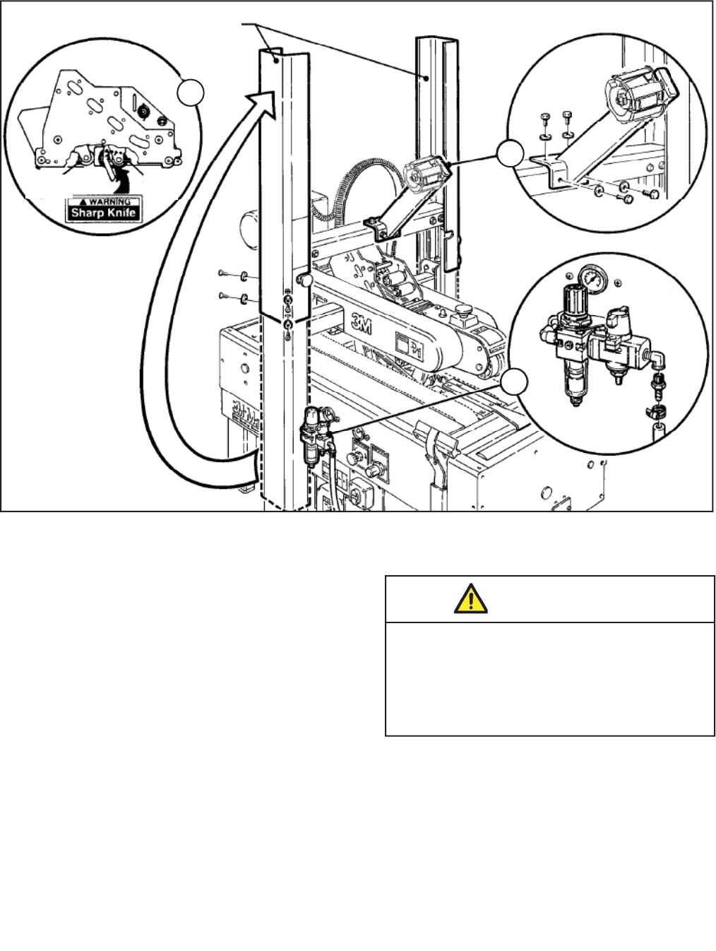
Figure 7-7 – 700r Frame Setup
700r-NA
2011 July
Column Guards
Buff ng
Roller
Cable
Tie
C
A
B
Note:
Column Guards
are removed
before
Installing the
Bumper Supports
(see Figure 2-6
and Figure 6-1).
Column Guards
are then
reinstalled
(as shown in a
rotated 180°
position)
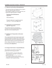
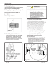
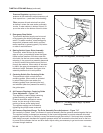
7. Hold taping head BUFFING ROLLER and cut
and remove cable tie that holds applying/buffi ng
arms retracted (Applying/buffi ng rollers are held
retracted for shipment - See Figure 7-6).
Allow buffi ng/applying arms to extend slowly.
Also cut and remove cable tie at rear of
lower taping head.
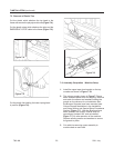
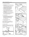
8. Check for free action of both upper and lower
taping heads. Push buffi ng roller into head to
check for free, smooth action of taping heads.
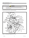
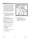
9. Ensure that the tape drum bracket assembly,
located on the lower taping head, is mounted
straight down, as shown in Figure 7-8A. The
tape drum bracket assembly can be pivoted to
provide tape roll clearance in certain cases.
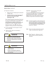
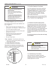
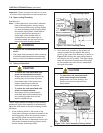
• To reduce the risk associated with sharp
blade hazards:
− Keep hands and fi ngers away from tape
cutoff blades under orange blade
guards. The blades are extremely sharp
WARNING