


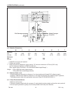

24
7-INSTALLATION AND SETUP (continued)
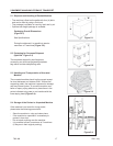
7.12 Box Size Capacity of Case Sealer
At its factory setting, the case sealer handles box
sizes up to 620mm [24.5 inch] maximum height
(See Specif cations Section). If larger capacity is
needed, the machine can be adjusted to accom-
modate boxes up to 725mm [28.5 inch] high.
Refer to "Special Setup Procedure – Box and
Machine Bed Height Range."
Note – Adjusting machine to accommodate 725mm
[28.5 inch] high boxes also increases minimum box
size to 170mm [6.8 inch] - See Parts list.
7.14 Initial Start-Up of Case Sealer
After completing the "Installation and Setup"
procedure, continue through "Operation" for tape
loading and start-up to be sure case sealer is
properly adjusted to run boxes.
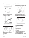
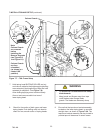
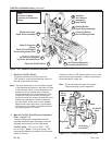
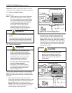
7.13 Electrical Connections and Controls
The electrical control box and "On/Off" switch are
located on the lower left side of the machine frame
(Figure 7-13). If desired, for operator convenience,
the "On/Off" switch can be relocated to the right
side of the machine frame. The receptacle providing
this service shall be properly grounded. Before
the power cord is plugged in, make sure that all
packaging materials and tools are removed from the
machine.
Do not plug electrical cord into outlet until ready
to run machine.
• To reduce the risk associated with
impact hazards:
− Always use appropriate supporting
means when working under the upper
drive assembly
• To reduce the risk associated with
mechanical and electrical hazards:
− Allow only properly trained and
qualifi ed personnel to operate and/or
service this equipment
WARNING
• To reduce the risk associated
with hazardous voltage:
− Position electrical cord away from foot
and/or vehicle traffi c
WARNING
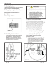
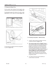
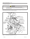
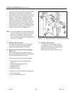
7.11 Bumper Supports (Upper Drive Assembly)
With the Safety Guard removed (see Installation and
Setup / Figure 7-7):
• Raise and lock the upper drive assembly in the
raised position. See "Operation – Mechanical Latch."
• Turn off air supply and electric power.
• Remove the Column Bumper and set screw parts
package from the carton.
• Using set screws provided, install Column
Bumper (the recommended position is
shown Below).
• Re-install Safety Guard.
* Note - Important - Some bumper positions may:
1) Allow upper and lower taping heads to come into
contact with each other.
2) Create added stress to the bumper.
3) Cause a malfunction of the machine.
These events can potentially cause damage to the
machine. For more information on bumper settings,
contact your 3M service representative.
Do Not
Use
Bottom
Holes
700r-NA
2011 July