


11 - SET UP AND ADJUSTMENTS
37
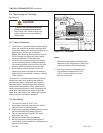
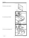
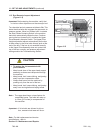
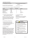
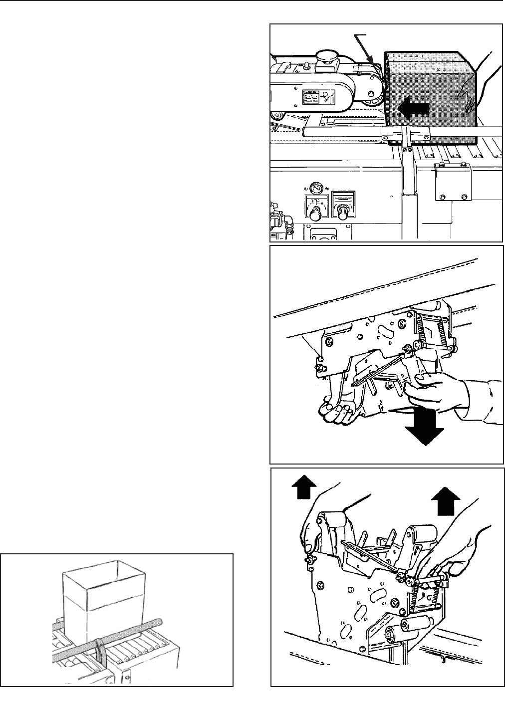
Upper Drive
Actuator Switch
2011 July
700r-NA
Figure 11-1
Figure 11-2
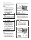
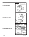
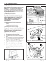
11.1 Box Width Adjustment
Boxes are automatically centered by the Side Guides
(Figure 11-1). The Side Guides are triggered by
the Centering Guide Switch which is located on the
machine bed. Side Guides air pressure adjustments
can be made using the Centering Guide Air Pressure
Regulator (See Figure 9-8).
11.2 Box Height Adjustment
Box Height is automatically determined when the
Upper Drive Assembly Actuator Switch is engaged
which is located on the front of the Upper Drive
Assembly (See Figure 11-2). .The Upper Drive air
pressure adjustments can be made using the
Centering Guide Air Pressure Regulator
(See Figure 9-8).
11.3 Adjustment of Top Flap Compression
Rollers
(Not Applicable to this Machine)
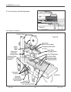
11.4 Changing the Tape Leg Length
Taping heads are preset to apply 70mm [2.75 inches]
long tape legs. To change tape leg length to 50mm
[2.0 inches], refer to Instructions below and also to
Manual 2, "Removing Taping Heads Procedure -
Changing the Tape Leg Length".
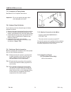
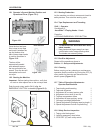
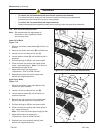
With upper drive assembly in raised position:
1. Remove tape from upper taping head.
2. Pivot up the clamp that secures the upper taping
head.
3. Hold upper taping head applying and buffi ng arms
from under upper assembly, slide head forward
and down to remove. See Figure 11-3.
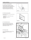
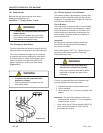
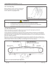
4. Lift the lower taping head, shown in Figure 11-4,
straight up to remove it from the case sealer
bed.
5. Refer to Manual 2, "Adjustments – Changing
Tape Leg Length," for taping head Setup.
6. Replace taping heads reverse of disassembly.
Turn on air supply and electric power, unlatch
upper drive assembly and allow it to return to its
rest position.
Figure 11-3 – Remove Upper Taping Head
Figure 11-4 – Remove Lower Taping Head