STARTING EQUIPMENT
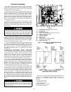
The 19XL requires a motor starter to operate the centrif-
ugal hermetic compressor motor, the oil pump, and various
auxiliary equipment. The starter serves as the main field
wiring interface for the contractor.
Three types of starters are available from Carrier Cor-
poration: solid-state, wye-delta, and across-the-line starters.
See Carrier Specification Z-375 for specific starter require-
ments. All starters must meet these specifications in order
to properly start and satisfy mechanical safety requirements.
Starters may be supplied as separate, free-standing units, or
may be mounted directly on the chiller (unit mounted) for
low-voltage units only.
Inside the starter are 3 separate circuit breakers. Circuit
breaker CB1 is the compressor motor circuit breaker. The
disconnect switch on the starter front cover is connected to
this breaker. Circuit breaker CB1 supplies power to the com-
pressor motor.
The main circuit breaker (CB1) on the front of the starter
disconnects the main motor current only. Power is still
energized for the other circuits. Two more circuit break-
ers inside the starter must be turned off to disconnect
power to the oil pump, PIC controls, and oil heater.
Circuit breaker CB2 supplies power to the control center,
oil heater, and portions of the starter controls. Circuit breaker
CB3 supplies power to oil pump. Both of these circuit break-
ers are wired in parallel with CB1 so that power is supplied
to them if the CB1 disconnect is open.
All starters are shipped with a Carrier control module called
the Starter Management Module (SMM). This module
controls and monitors all aspects of the starter. See the Con-
trols section on page 11 for additional SMM information.
All starter replacement parts are supplied by the starter
manufacturer.
Unit-Mounted Solid-State Starter (Optional)
—
The 19XL may be equipped with a solid-state, reduced-
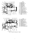
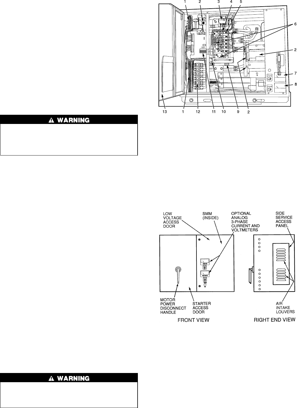
voltage starter (Fig. 5 and 6). This starter provides on-off
control of the compressor motor as its primary function.
Using this type of starter reduces the peak starting torque,
reduces the motor inrush current, and decreases mechanical
shock. This is summed up by the phrase ‘‘soft starting.’’
Two varieties of solid-state starters are available as a 19XL
option (factory supplied and installed). When a unit-mounted,
optional, solid-state starter is purchased with the 19XL, a
Benshaw, Inc. solid-state starter will be shipped with the unit.
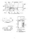
See Fig. 5. The solid-state starter’s manufacturer name will
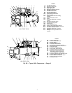
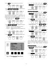
be located inside the starter access door. See Fig. 6.
These starters operate by reducing the starting voltage. The
starting torque of a motor at full voltage is typically 125%
to 175% of the running torque. When the voltage and the
current are reduced at start-up, the starting torque is reduced
as well. The object is to reduce the starting voltage to just
the voltage necessary to develop the torque required to get
the motor moving. The voltage and current are then ramped
up in a desired period of time. The voltage is reduced through
the use of silicon controlled rectifiers (SCR). Once full volt-
age is reached, a bypass contactor is energized to bypass the
SCRs.
When voltage is supplied to the solid-state circuitry, the
heat sinks within the starter are at line voltage. Do not
touch the heat sinks while voltage is present or serious
injury will result.
There are a number of LEDs (light-emitting diodes) that
are useful in troubleshooting and starter check-out on
Benshaw, Inc. solid-state starters. These are used to
indicate:
• voltage to the SCRs
• SCR control voltage
• power indication
• proper phasing for rotation
• start circuit energized
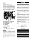
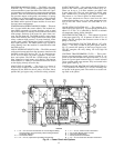
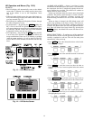
LEGEND
1—Field Wiring Terminal Strips (TB2 and TB3)
2—Circuit Breaker 1, 2, 3, 4
3—Overload Unit
4—Solid-State Controller
5—Silicon Controlled Rectifier (SCR) LED (One of 6)
6—Starter Fault and Run LEDs
7—Voltmeter (Optional)
8—Ammeter (Optional)
9—SCR (One of 6)
10 — Voltage LED
11 — Starter Management Module (SMM)
12 — Pilot Relays (PR1 to PR5)
13 — Starter Access Door
Fig. 5 — Benshaw, Inc. Solid-State Starter,
Internal View
Fig.6—Typical Starter External View
(Solid-State Starter Shown)
10


