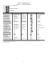
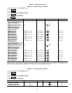
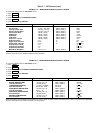
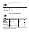
High Discharge Temperature Control — If the
discharge temperature increases above 160 F (71.1 C)
(PSIO Software Version 09 and higher) or 180 F (82 C) (PSIO
Software Version 08 or lower), the guide vanes are propor-
tionally opened to increase gas flow through the compressor.
If the leaving chilled water temperature is then brought 5° F
(2.8° C) below the control set point temperature, the con-
trols will bring the chiller into the recycle mode.
Oil Sump Temperature Control — The oil sump tem-
perature control is regulated by the PIC which uses the oil
heater relay when the chiller is shut down.
As part of the pre-start checks executed by the controls,
oil sump temperature is compared against evaporator refrig-
erant temperature. If the difference between these 2 tem-
peratures is 50 F (27.8 C) or less, the start-up will be delayed
until the oil temperature is 50 F (27.8 C) or more. Once this
temperature is confirmed, the start-up continues.
PSIO SOFTWARE VERSION 08 AND LOWER — The oil
heater relay is energized whenever the chiller compressor is
off, and the oil sump temperature is less than 140 F (60 C)
or sump temperature is less than the cooler refrigerant tem-
perature plus 60° F (33.3° C). The heater is then turned
off when the oil sump temperature is: 1) more than
160 F (71.1 C); or 2) the sump temperature is more than
145 F (62.8 C) and more than the cooler refrigerant tem-
perature plus 65° F (36.1° C). The heater is always off dur-
ing start-up or when the compressor is running.
PSIO SOFTWARE VERSION 09AND HIGHER — The oil
heater relay is energized whenever the chiller compressor is
off and the oil sump temperature is less than 150 F (65.6 C)
or the oil sump temperature is less than the cooler refrig-
erant temperature plus 70° F (39° C). The oil heater is turned
off when the oil sump temperature is either 1) more than
160 F (71.1 C); or 2) the oil sump temperature is more than
155 F (68.3 C) and more than the cooler refrigerant tem-
perature plus 75° F (41.6° C). The oil heater is always off
during start-up or when the compressor is running.
When a power failure to the PSIO module has occurred
for more than 3 hours (i.e., initial start-up), the oil sump is
heated to 100° F (56° C) above the evaporator refrigerant
temperature or 190 F (88 C), whichever is lower. Once this
temperature is reached, the oil pump will be energized for
1 to 2 minutes or until the oil sump temperature cools to
below 145 F (63 C). The normal heating algorithm is now
followed once ramp loading has been completed.
After a 3-hour power failure, the oil temperature must rise
to the higher oil temperature. The controls will delay the start
of the compressor until this temperature is met.
Oil Cooler — The oil must be cooled when the compres-
sor is running. This is accomplished through a small, plate-
type heat exchanger located behind the oil pump. The heat
exchanger uses liquid condenser refrigerant as the cooling
liquid.Arefrigerant thermostatic expansion valve (TXV) regu-
lates refrigerant flow to control oil temperature entering the
bearings. There is always a flow of refrigerant bypassing the
thermostatic TXV. The bulb for the expansion valve is strapped
to the oil supply line leaving the heat exchanger and the valve
is set to maintain 110 F (43 C).
NOTE: The TXV is not adjustable. Oil sump temperature
may be at a lower temperature.
Remote Start/Stop Controls — Aremote device, such
as a time clock which uses a set of contacts, may be used to
start and stop the chiller. However, the device should not be
programmed to start and stop the chiller in excess of 2 or
3 times every 12 hours. If more than 8 starts in 12 hours
occur, then an Excessive Starts alarm is displayed, prevent-
ing the chiller from starting. The operator must reset the alarm
at the LID in order to override the starts counter and start
the chiller. If Automatic Restart After a Power Failure is not
activated when a power failure occurs, and the remote con-
tact is closed, the chiller will indicate an alarm because of
the loss of voltage.
The contacts for Remote Start are wired into the starter at
terminal strip TB5, terminals 8A and 8B. See the certified
drawings for further details on contact ratings. The contacts
must be dry (no power).
Spare Safety Inputs — Normally closed (NC) digital
inputs for additional field-supplied safeties may be wired to
the spare protective limits input channel in place of the factory-
installed jumper. (Wire multiple inputs in series.) The open-
ing of any contact will result in a safety shutdown and LID
display. Refer to the certified drawings for safety contact
ratings.
Analog temperature sensors may also be added to the
options modules, if installed. These may be programmed to
cause an alert on the CCN network, but will not shut the
chiller down.
SPARE ALARM CONTACTS — Two spare sets of alarm
contacts are provided within the starter. The contact ratings
are provided in the certified drawings. The contacts are
located on terminal strip TB6, terminals 5A and 5B, and
terminals 5C and 5D.
Condenser Pump Control — The chiller will moni-
tor the CONDENSER PRESSUREand may turn on this pump
if the pressure becomes too high whenever the compressor
is shut down. CONDENSER PRESSURE OVERRIDE is used
to determine this pressure point. This value is found on the
Equipment Service1 LID table and has a default value
(Table 4). If the CONDENSER PRESSURE is greater than
or equal to the CONDENSER PRESSURE OVERRIDE, and
the ENTERING CONDENSER WATER TEMP (Temper-
ature) is less than 115 F (46 C), then the condenser pump
will energize to try to decrease the pressure. The pump will
turn off when the condenser pressure is less than the
pressure override less 5 psi (34 kPa), or the CONDENSER
REFRIG (Refrigerant) TEMP is within 3° F (2° C) of the
ENTERING CONDENSER WATER temperature.
Condenser Freeze Prevention — This control
algorithm helps prevent condenser tube freeze-up by ener-
gizing the condenser pump relay. If the pump is controlled
by the PIC, starting the pump will help prevent the water in
the condenser from freezing. Condenser freeze prevention
can occur whenever the chiller is not running except when
it is either actively in pumpdown or in Pumpdown Lockout
with the freeze prevention disabled (refer to Control Test table,
Pumpdown/Terminate Lockout tables).
When the CONDENSER REFRIG TEMP is less than
or equal to the CONDENSER FREEZE POINT,orthe
ENTERING CONDENSER WATER temperature is less than
or equal to the CONDENSER FREEZE POINT, then the
CONDENSER WATER PUMP shall be energized until the
CONDENSER REFRIG TEMP is greater than the CON-
DENSER FREEZE POINT plus 5° F (2.7° C). An alarm will
be generated if the chiller is in PUMPDOWN mode and the
pump is energized. An alert will be generated if the chiller
is not in PUMPDOWN mode and the pump is energized. If
in recycle shutdown, the mode shall transition to a non-
recycle shutdown.
32


