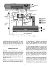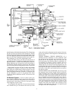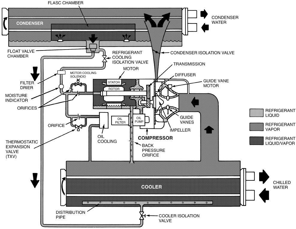
Refrigerant that flows to the oil cooling system is reg-
ulated by a thermostatic expansion valve. There is always
a minimum flow bypassing the TXV, which flows through
an orifice. The TXV valve regulates flow into the oil/
refrigerant plate and frame-type heat exchanger. The bulb
for the expansion valve controls oil temperature to the bear-
ings. The refrigerant leaving the heat exchanger then returns
to the cooler.
LUBRICATION CYCLE
Summary —
The oil pump, oil filter, and oil cooler make
up a package located partially in the transmission casting of
the compressor-motor assembly. The oil is pumped into a
filter assembly to remove foreign particles, and is then forced
into an oil cooler heat exchanger where the oil is cooled to
proper operational temperatures. After the oil cooler, part of
the flow is directed to the gears and the high speed shaft
bearings; the remaining flow is directed to the motor shaft
bearings. Oil drains into the transmission oil sump to com-
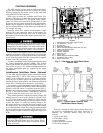
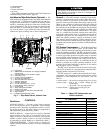
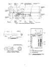
plete the cycle (Fig. 4).
Details — Oil is charged into the lubrication system through
a hand valve. Two sight glasses in the oil reservoir permit oil
level observation. Normal oil level is between the middle of
the upper sight glass and the top of the lower sight glass
when the compressor is shut down. The oil level should be
visible in at least one of the 2 sight glasses during operation.
Oil sump temperature is displayed on the LID default
screen. Oil sump temperature ranges during compressor
operation between 100 to 120 F (37 to 49 C) [120 to 140 F
(49 to 60 C)].
The oil pump suction is fed from the oil reservoir. An
oil pressure relief valve maintains 18 to 25 psid (124 to
172 kPad) differential pressure in the system at the pump
discharge. This differential pressure can be read directly from
the Local Interface Device (LID) default screen. The oil pump
discharges oil to the oil filter assembly. This filter can be
valved closed to permit removal of the filter without drain-
ing the entire oil system (see Maintenance sections, pages
61 to 65, for details). The oil is then piped to the oil cooler.
This heat exchanger uses refrigerant from the condenser as
the coolant. The refrigerant cools the oil to a temperature
between 100 and 120 F (37 to 49 C).
As the oil leaves the oil cooler, it passes the oil pressure
transducer and the thermal bulb for the refrigerant expan-
sion valve on the oil cooler. The oil is then divided, with a
portion flowing to the thrust bearing, forward pinion bear-
ing, and gear spray. The balance then lubricates the motor
shaft bearings and the rear pinion bearing. The oil temper-
ature is measured as the oil leaves the thrust and forward
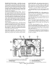
Fig. 3 — Refrigerant Motor Cooling and Oil Cooling Cycles
8


