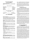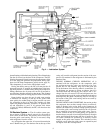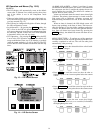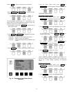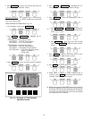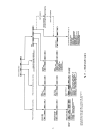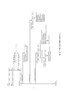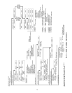
PROCESSOR MODULE (PSIO) — The PSIO is the brain
of the PIC (Fig. 11). This module contains all the operating
software needed to control the chiller. The 19XLuses 3 pres-
sure transducers and 8 thermistors to sense pressures and tem-
peratures. These are connected to the PSIO module. The PSIO
also provides outputs to the guide vane actuator, oil pump,
oil heater, hot gas bypass (optional), motor cooling solenoid,
and alarm contact. The PSIO communicates with the LID,
the SMM, and the optional 8-input modules for user inter-
face and starter management.
STARTER MANAGEMENT MODULE (SMM) — This mod-
ule is located within the starter cabinet. This module ini-
tiates PSIO commands for starter functions such as start/
stop of the compressor, start/stop of the condenser and chilled
water pumps, start/stop of the tower fan, spare alarm con-
tacts, and the shunt trip. The SMM monitors starter inputs
such as flow switches, line voltage, remote start contact, spare
safety, condenser high pressure, oil pump interlock, motor
current signal, starter 1M and run contacts, and kW trans-
ducer input (optional). The SMM contains logic capable of
safely shutting down the machine if communications with
the PSIO are lost.
LOCALINTERFACE DEVICE (LID) — The LID is mounted
to the control center and allows the operator to interface with
the PSIO or other CCN devices (Fig. 11). It is the input cen-
ter for all local chiller set points, schedules, set-up func-
tions, and options. The LID has a STOP button, an alarm
light, 4 buttons for logic inputs, and a display. The function
of the 4 buttons or ‘‘softkeys’’are menu driven and are shown
on the display directly above the key.
6-PACK RELAY BOARD — This device is a cluster of
6 pilot relays located in the control center (Fig. 11). It is
energized by the PSIO for the oil pump, oil heater, alarm,
optional hot gas bypass relay, and motor cooling solenoid.
8-INPUT MODULES — One optional module is factory in-
stalled in the control center panel when ordered (Fig. 11).
There can be up to 2 of these modules per chiller with
8 spare inputs each. They are used whenever chilled water
reset, demand reset, or reading a spare sensor is required.
The sensors or 4 to 20 mA signals are field-installed.
The spare temperature sensors must have the same
temperature/resistance curve as the other temperature sen-
sors on this unit. These sensors are 5,000 ohm at 75 F
(25 C).
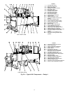
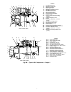
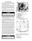
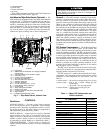
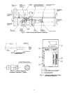
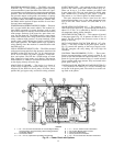
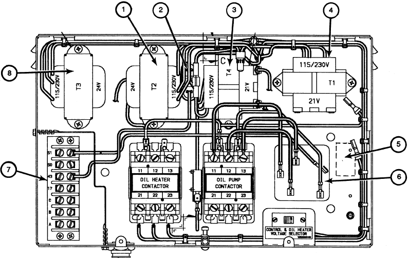
OIL HEATER CONTACTOR (1C) — This contactor is lo-
cated in the power panel (Fig. 12) and operates the heater at
either 115 or 230 v. It is controlled by the PIC to maintain
oil temperature during chiller shutdown.
OIL PUMP CONTACTOR (2C) — This contactor is located
in the power panel (Fig. 12). It operates all 200 to 575-v oil
pumps. The PIC energizes the contactor to turn on the oil
pump as necessary.
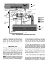
HOT GAS BYPASS CONTACTOR RELAY (3C) (Op-
tional) — This relay, located in the power panel, (Item 5,
Fig. 12) controls the opening of the hot gas bypass valve.
The PIC energizes the relay during low load, high lift
conditions.
CONTROL TRANSFORMERS (T1-T4) — These trans-
formers convert incoming control voltage to either 21 vac
power for the PSIO module and options modules, or 24 vac
power for 3 power panel contactor relays, 3 control solenoid
valves, and the guide vane actuator. They are located in the
power panel. See Fig. 12.
CONTROLANDOIL HEATER VOLTAGE SELECTOR (S1)
— It is possible to use either 115 v or 230 v incoming con-
trol power in the power panel. The switch is set to the volt-
age used at the jobsite.
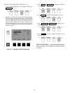
LEGEND
1—T2 — 24 vac Power Transformer for Hot Gas Bypass Relay,
Oil Pump Relay, Oil Heater Relay, Motor Cooling Solenoid,
Oil Reclaim Solenoid
2—Oil Pressure Switch
3—T4 — 24 vac, Optional 8-Input Module Transformer
Fig. 12 — Power Panel with Options
4—T1 — 24 vac, Control Center Transformer
5—3C Hot Gas Bypass Relay Location
6—Oil Pump Terminal Block
7—Factory Terminal Connections
8—T3 — 24 vac Guide Vane Actuator Transformer
13


