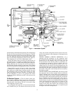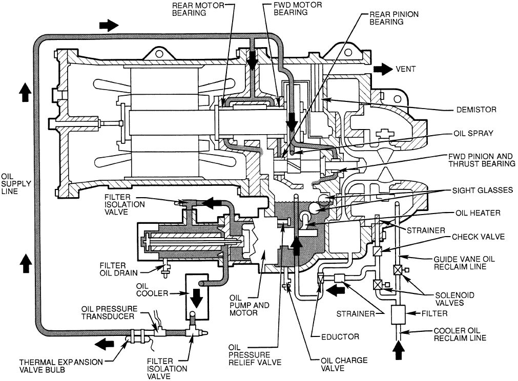
journal bearings within the bearing housing.The oil then drains
into the oil reservoir at the base of the compressor. The PIC
(Product Integrated Control) measures the temperature of the
oil in the sump and maintains the temperature during shut-
down (see Oil Sump Temperature Control section, page 32).
This temperature is read on the LID default screen.
During the chiller start-up, the PIC will energize the oil
pump and provide 15 seconds of prelubrication to the bear-
ings after pressure is verified before starting the compressor.
During shutdown, the oil pump will run for 60 seconds to
post-lubricate after the compressor shuts down. The oil pump
can also be energized for testing purposes in the Control Test.
Ramp loading can slow the rate of guide vane opening
to minimize oil foaming at start-up. If the guide vanes
open quickly, the sudden drop in suction pressure can cause
any refrigerant in the oil to flash. The resulting oil foam
cannot be pumped efficiently; therefore, oil pressure falls
off and lubrication is poor. If oil pressure falls below
15 psid (103 kPad) differential, the PIC will shut down the
compressor.
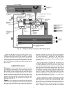
Oil Reclaim System — The oil reclaim system oper-
ates to return oil back to the oil reservoir by recovering it
from 2 areas on the chiller. The primary area of recovery is
from the guide vane housing. Oil also is recovered, along
with refrigerant, from the cooler.
Any refrigerant that enters the oil reservoir/transmission
area is flashed into gas. The demister line at the top of the
casing will vent this refrigerant into the suction of the com-
pressor. Oil entrained in the refrigerant is eliminated by the
demister filter.
DURING NORMAL CHILLER OPERATION, oil is
entrained with the refrigerant. As the compressor pulls
the refrigerant into the guide vane housing to be com-
pressed, the oil will normally drop out at this point and
fall to the bottom of the housing where it accumulates. Us-
ing discharge gas pressure to power an eductor, the oil is
vacuumed from the housing by the eductor and is dis-
charged into the oil reservoir. Oil and refrigerant are also
recovered from the top of the cooler refrigerant level and are
discharged into the guide vane housing. The oil will drop to
the bottom of the guide vane housing and be recovered by
the eductor system.
DURING LIGHT LOAD CONDITIONS, the suction gas into
the compressor does not have enough velocity to return oil,
which is floating in the cooler back to the compressor. In
addition, the eductor may not have enough power to pull the
oil from the guide vane housing back into the oil reservoir
due to extremely low pressure at the guide vanes. Two so-
lenoids, located on the oil reclaim piping, are operated so
that the eductor can pull oil and refrigerant directly from the
cooler and discharge the mixture into the oil reservoir. The
oil reclaim solenoids are operated by an auxiliary contact
integral to the guide vane actuator. This switchover of the
solenoids occurs when the guide vanes are opened beyond
30 degrees from the closed position.
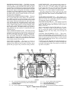
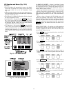
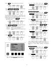
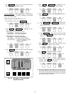
Fig. 4 — Lubrication System
9


