3. Some dashpot-type magnetic overload relays must be filled
with oil on the jobsite. If the starter is equipped with de-
vices of this type, remove the fluid cups from these mag-
netic overload relays.Add dashpot oil to cups per instructions
supplied with the starter. The oil is usually shipped in a
small container attached to the starter frame near the re-
lays. Use only dashpot oil supplied with the starter. Do
not substitute.
Factory-filled dashpot overload relays need nooil atstart-up
and solid-state overload relays do not have oil.
4. Reapply starter control power (not main chiller power)to
check electrical functions. When using a reduced-voltage
starter (such as a wye-delta type) check the transition timer
for proper setting. The factory setting is 30 seconds
(± 5 seconds), timed closing. The timer is adjustable in a
range between 0 and 60 seconds and settings other than
the nominal 30 seconds may be chosen as needed (typi-
cally 20 to 30 seconds are used).
When the timer has been set, check that the starter (with
relay 1CR closed) goes through a complete and proper
start cycle.
BENSHAW, INC. SOLID-STATE STARTER
This equipment is at line voltage when AC power is
connected. Pressing the STOP button does not remove
voltage. Use caution when adjusting the potentiometers
on the equipment.
1. Check that all wiring connections are properly termi-
nated to the starter.
2. Verify that the ground wire to the starter is installed prop-
erly and is of sufficient size.
3. Verify that the motors are properly grounded to the starter.
4. Check that all of the relays are properly seated in their
sockets.
5. Verify that the proper ac input voltage is brought into the
starter per the certified drawings.
6. Verify the initial factory settings of the starting torque and
ramp potentiometers are set per the note on the schematic
for the starters.
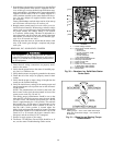
NOTE: The potentiometers are located at the lower left
hand corner on the circuit board mounted in front of the
starter power stack (Fig. 30 and 31).
The starting torque potentiometer should be set so that
when the PIC calls for the motor to start, the rotor should
just start to turn. The nominal dial position for a 60 Hz
motor is approximately the 11:30 position. The nominal
dial position for a 50 Hz motor is approximately in the
9:30 position because the board is turned on its side, so
that the 9:00 o’clock position is located where the
6:00 o’clock position would normally be located. The ramp
potentiometer should be set so that the motor is up to full
speed in 15 to 20 seconds, the bypass contactors have
energized, and the auxiliary LCD is energized.
7. Proceed to apply power to the starter.
8. The Power +15 and Phase Correct LEDs should be on. If
not, see the starter Troubleshooting Guide section.
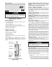
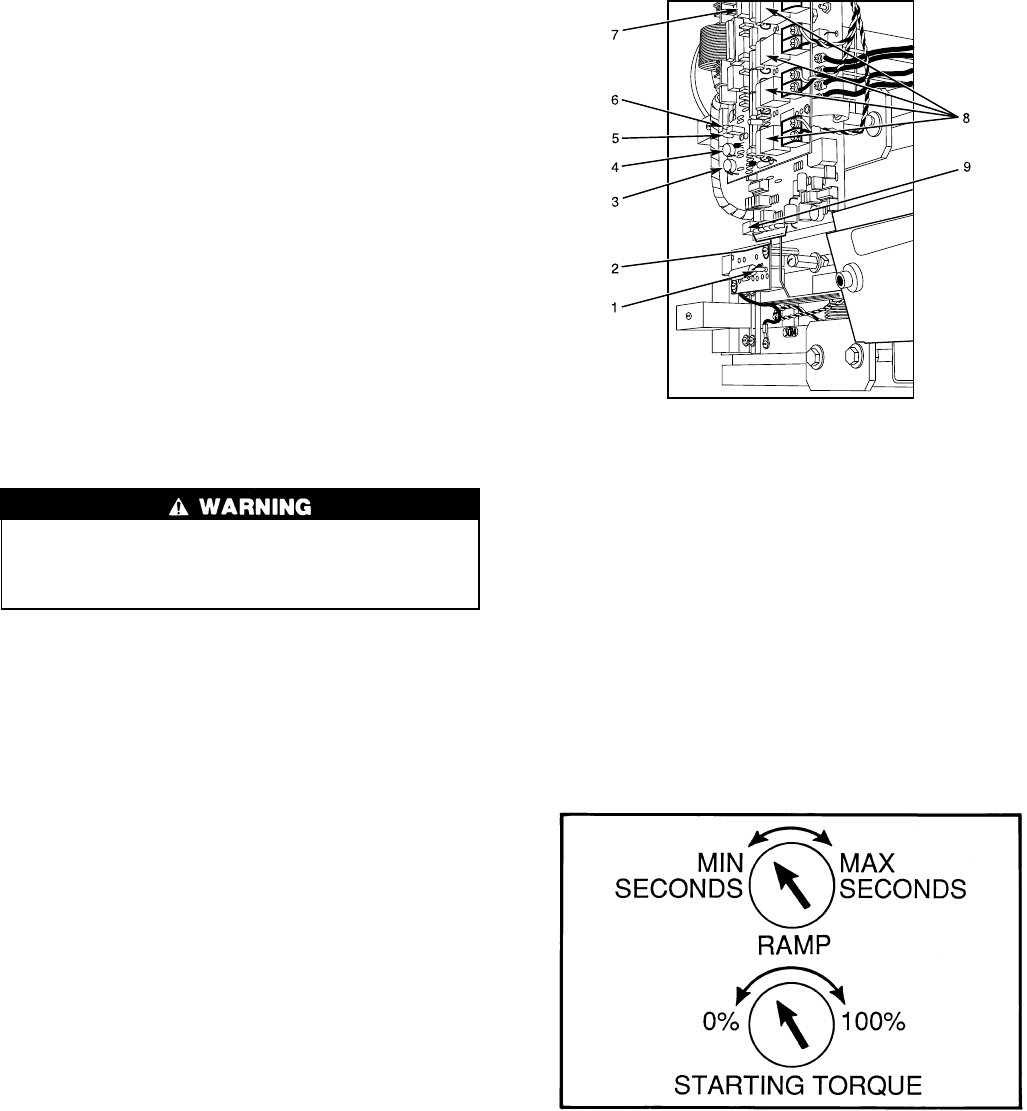
LEGEND
1—Phase Voltage Indicator
2—Starter Fault and Run LEDs (5)
• Overtemp
• Ground Fault
• Current Unbalance (CUB)
While Stopped
• Current Unbalance
• Run (Start Initiated)
3—Starting Torque Potentiometer
4—Ramp Up Potentiometer
5—Phase Correct LED
6—Relay On LED
7—Power +15 and Auxiliary (Starter
in RUN State) LEDs (Hidden)
8—SCR Indicator LEDs (Hidden)
9—Reset Button
Fig. 30 — Benshaw, Inc. Solid-State Starter
Power Stack
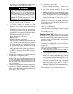
NOTE: Adjustments:
Starting torque — 0% to 100% rated motor torque.
Ramp time to full motor voltage — 0.5 seconds to
60 seconds.
Fig. 31 — Ramp Up and Starting Torque
Potentiometers
49


