


GFK-1115 Appendix A Cabling Information A - 5
A
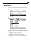
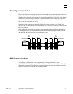
Connecting Devices to the Bus
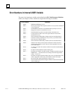
Devices can be placed in any physical sequence on the bus, however, communications will be most
efficient if devices are placed in the same sequence as their Device Numbers (Block
Numbers).Each device has four terminals for the serial bus cable (Serial 1, Serial 2, Shield In, and
Shield Out). Connect the Serial 1 terminal of each block to the Serial 1 terminals of the previous
device and the next device. Connect the Serial 2 terminal of each block to the Serial 2 terminals of
the previous device and the next device.
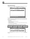
Shield In of each block must be connected to Shield Out of the preceding device. For the first
device on the bus, Shield In can be left unconnected. For the last device on the bus, Shield Out can
be left unconnected.
When making bus connections, the maximum exposed length of bare wires should be two inches.
For added protection, each shield drain wire should be insulated with spaghetti tubing to prevent
the Shield In and Shield Out wires from touching each other.
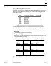
START
OF
BUS
SERIAL 1
SERIAL 2
SHIELD IN
SHIELD OUT
TERMINATING
RESISTOR
a40743
SERIAL 1
SERIAL 2
SHIELD IN
SHIELD OUT
TERMINATING
RESISTOR
END
OF
BUS
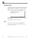
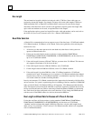
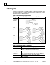
SNP Communications
To configure an SNP interface, refer to Appendix A (“Cabling Information”) in the
PANELWARE™ MMI Application Manual fro GE Fanuc Series 90 Protocol (SNP) —
GFK-0850.
The specific information you will need is contained in the specifications and cabling diagrams for
an RS-232 interface to IF0 and IF1 of the C200 Controller.