


GFK-1115 Chapter 4 Configuring Communication with the PLC 4 - 5
4
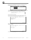
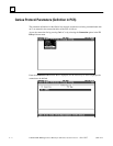
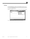
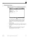
PLC Node Parameter Definitions
Additional information must be supplied for every defined connection except for an Internal or
GENIUS Internal connection. Use the cursor keys to highlight the desired connection, then press
the F4 PLC Node Parameters key to access the PLC Node Parameter Definition window.
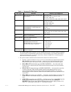
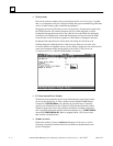
Note
In most instances, the default settings indicated in the window will suffice. The
one exception is the Target device number setting, which must be set to match
the Genius bus address of the device represented by the connection. Parameters
indicated by an * must correspond to the configuration of the PLC interface at
the other end.
❏ Target device number*
This is the Genius serial bus address, or device number, of the device represented by the
connection. This value ranges between 0 and 31, inclusive, and must be provided for
every connection.
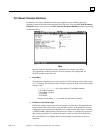
❏ Taskname*
This parameter must be specified only if you wish to access %P or %L data via a
Series 90-70 GBC. If you do wish to specify it, supply the 1 — 7-character
Taskname of the program running in the 90-70 CPU.