


A - 6 PANELWARE MMI Application Manual for GE Fanuc Genius Protocol - June 1995 GFK-1115
A
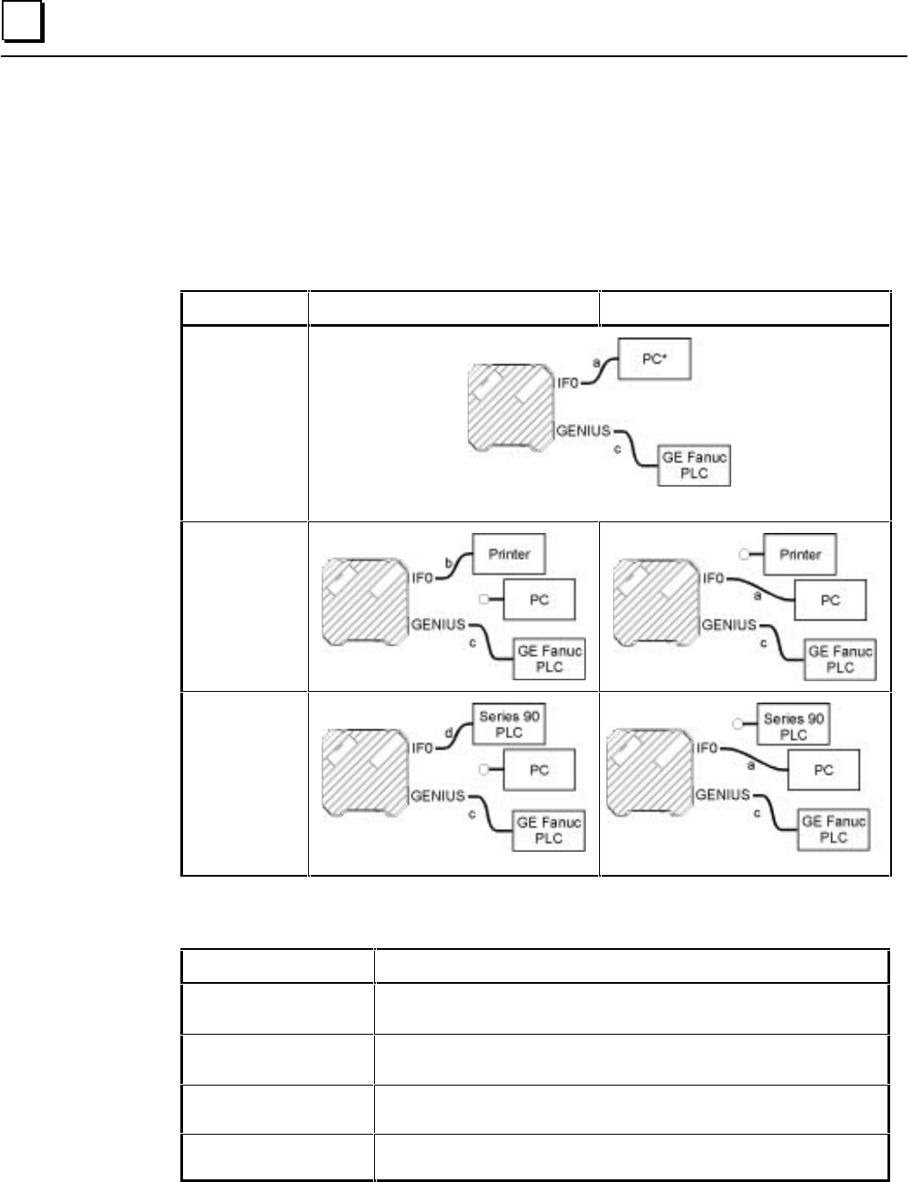
Cable Diagrams
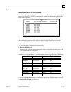
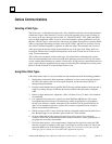
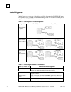
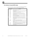
Table A-2 provides an overview of the cabling possibilities for connecting PANELWARE Panels,
PLCs, printers and PCs (with PCS installed and running). Table A-3 lists the locations of pin-out
diagrams in the PANELWARE documentation.
Table A - 2. Cable Diagrams for Various Configurations
Configuration Run Mode Teach Mode
C400
+ Series 90 PLC
(no printer)
* The PC does not need to be connected in RUN mode.
C400
+ Series 90 PLC
+ printer on IF0
C400
+ Series 90 PLC
(serial)
+GE Fanuc PLC
(Genius)
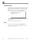
Table A - 3. Pin-out Diagram Locations in Documentation
Cable (see Table A-1) Manual and Chapter/Appendix
a (Panel to PC)
PANELWARE Hardware Installation User's Manual (GFK-0848)
Appendix A Cabling Information (Connection to the PC)
b (Panel to printer)
PANELWARE Hardware Installation User's Manual (GFK-0848)
Chapter 7 “Printers”
c (Panel to CPU —
Genius)
Pages A-2 through A-6,
PANELWARE MMI Application Manual for
GE Fanuc Genius Protocol
— GFK-1115 (this manual)
d (Panel to CPU — SNP)
PANELWARE™ MMI Application Manual for GE Fanuc Series 90 Protocol
(SNP) —
GFK-0850