


10
1
1
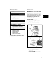
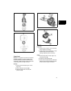
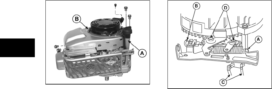
Figure 3
6. Using a torque wrench and socket to fit the
flywheel nut, turn flywheel clockwise with
brake engaged. While turning at a steady
rate, torque reading should be 26 lb.-in.
(3 Nm) or higher.
7. If reading is low, check thickness of brake
pad. Replace brake assembly if thickness
is less than 0.09” (2.28mm).
8. If brake pad thickness is acceptable,
adjust control cable to position pad closer
to flywheel when safety control is in RUN
position.
9. Replace brake assembly if correct
adjustment cannot be made.
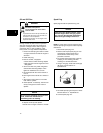
Inspect Brake and Switches
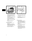
1. Disconnect spring from brake anchor
(A, Figure 4).
2. Disconnect stop switch wire from stop
switch (B). If engine is equipped with an
electric starter, disconnect both wires from
the starter interlock switch (C).
3. Remove two screws (D) from brake
bracket and remove bracket.
Figure 4
4. Inspect brake pad on brake lever. Replace
brake assembly if thickness is less than
0.09” (2.28mm).
5. Test stop switch as described in Section 2.
6. Test electric starter interlock switch as
described in Section 2.
Assemble Flywheel Brake
1. Install brake assembly on cylinder and
torque mounting screws to values listed in
Section 12 - Engine Specifications.
2. Install stop switch wire and bend end of
wire 90°. Install wires on interlock switch, if
equipped.
3. Install brake spring.
4. Actuate brake system to ensure proper
movement, then test brake torque as
previously described.
5. Install blower housing/rewind assembly,
install dipstick tube and dipstick, and
install fuel tank and static guard. Torque
all screws to values listed in Section 12 -
Engine Specifications.