


40
2
2
NOTICE: Connect test leads BEFORE starting
the engine. Be sure connections are secure. If a
test lead vibrates loose while engine is running,
the regulator-rectifier may be damaged.
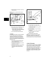
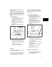
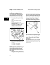
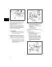
Use the DC Shunt #19468 (D, Figure 29) to
avoid blowing the fuse in the test meter when
testing the DC output of the 16 Amp system.
The DC Shunt must be installed to the negative
(-) terminal of the battery. All connections must
be clean and tight to obtain accurate readings.
1. Connect stator wire harness to regulator-
rectifier.
2. Install shunt to negative (-) battery
terminal.
3. Insert RED test lead (A) into V Ω
receptacle in meter. Connect to RED post
terminal (C) on shunt.
4. Insert BLACK test lead (B) into COM
receptacle in meter and connect to
BLACK post terminal (E) on shunt.
5. Rotate selector to 300mV position.
Figure 29
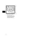
6. Run the engine at 3600 RPM. The output
should be:
• 3-10 Amps - 10 Amp System
• 3-16 Amps - 16 Amp System
NOTE: The amperage produced depends on the
battery voltage. If the battery is below 11 Volts,
the output reading would be 10 or 16 Amps,
depending upon the alternator system being
tested. The amperage will be less at maximum
battery voltage.
7. If NO or LOW output is found, be sure that
the regulator-rectifier is grounded properly
and all connections are clean and secure.
If there is still NO or LOW output, replace
the regulator-rectifier.
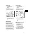
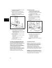
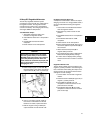
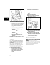
Regulator-Rectifier with Charge Indicator
The regulator-rectifier #493219 is used by OEMs
that have a charging indicator light instead of an
ammeter. In addition to the RED DC output wire
(A, Figure 30), the regulator-rectifier has a blue
wire (B) to activate a charging indicator light
when battery voltage is below 12 volts. The
connector has a raised rib (C) on the red wire
side to indicate the output side of the connector.
Figure 30
The charging indicator light should light when the
key switch in ON and the engine not running.
With the engine running, the charging indicator
light should go out, indicating that the charging
circuit is operating and the battery voltage in
above 12 volts.
The charge indicator light and wiring is supplied
by the OEM.
DC charging output values and test procedures
are the same as those listed for the 10 amp and
16 amp systems.