


96
6
6
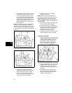
2. If head passes visual inspection, use Plug
Gauge #19122 to check valve guides for
wear. If gauge enters the guide 1/4” (6.4
mm) or more, replace the guide (models
97700, 99700) or replace the entire head
(models 110000, 120000, 150000). If plug
gauge is not available, see Section 12 -
Engine Specifications for the valve guide
reject dimension.
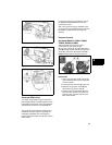
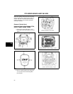
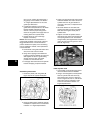
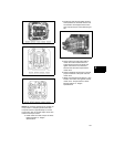
NOTE: To replace valve guides (models 97700,
99700), use Valve Guide Driver #19367 (A,
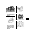
Figure 10) to press out the guides. Then, using
the same tool, press either end of the new guides
into the head until 1/8” (3.2 mm) above flush (A,
Figure 11).
Figure 10
Figure 11
3. If guides are replaced, or the original
guides still meet specifications, use Finish
Reamer #19066 and Reamer Guide
#19191 to ensure proper sizing and to
clean out the guides. Thoroughly clean all
reaming debris from cylinder head.
4. Inspect valves for wear or damage.
Replace if necessary.
NOTE: Valve faces can be resurfaced on a
commercially available valve grinder. However,
Briggs & Stratton does not recommend this
practice because the quality of the resurfacing
may be insufficient. Instead, valve replacement
is recommended.
5. Oil the intake valve guide and intake valve
stem, then insert valve into head.
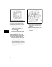
6. Using Valve Lapping Tool #19258 and
Lapping Compound #94150, lap valve and
seat together to assure a good sealing
surface. Remove valve, the repeat
procedure for the exhaust valve.
7. Thoroughly clean both valves and cylinder
head of all lapping compound residue.
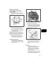
Assemble Cylinder Head
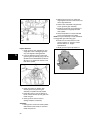
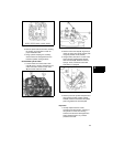
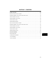
1. Install new plastic push rod guides into the
cylinder head plate (A, Figure 12) (models
110000, 120000, 150000). Using new
plate gasket, install the cylinder head
plate. Torque screws to values listed in
Section 12 - Engine Specifications.
Figure 12
2. Lightly coat valve stems with Valve Guide
Lubricant #93963. then insert valves into
cylinder head. Do not get lubricant on
valve face, valve seat, or exposed end of
valve stem.
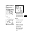
3. Oil inside diameter of new stem seal/
washer and install on intake valve stem.
Slide seal down against head plate or
cylinder head (A, Figure 13).