


137
10
10
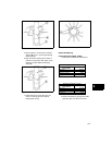
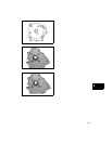
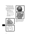
Figure 4
Figure 5
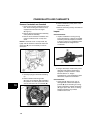
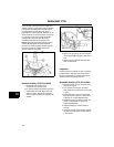
2. Using a dial caliper, measure the journal
diameters and cam lobes. Compare
results to values listed in Section 12 -
Engine Specifications. If wear exceeds the
reject dimensions, replace the camshaft.
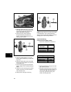
Install Crankshaft and Camshaft
1. Lubricate the cylinder bearing/oil seal with
engine oil.
2. Install intake and exhaust valve tappets.
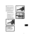
3. Support both ends of the crankshaft, and
carefully install into the cylinder.
NOTE: The counterbalance system, if equipped,
must be assembled to the crankshaft before
installing into the cylinder.
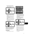
4. Assemble connecting rod assembly to
crankshaft.
5. Install the timing gear to the crankshaft
with timing mark out. The flange of the
gear must face the counterweight link, if
equipped.
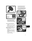
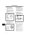
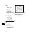
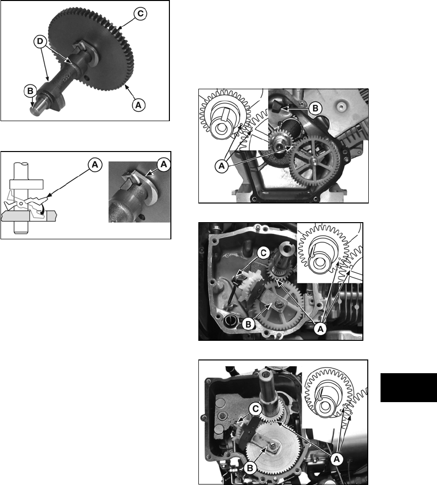
6. Install camshaft, making sure tappets clear
cam lobes. Timing marks
(A, Figures 6, 7, 8) must align.
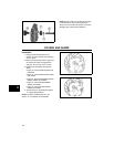
7. On horizontal crankshaft engines, make
sure the paddle on the governor shaft
(B, Figure 6) is rotated in line with the
governor cup inside the crankcase cover.
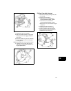
8. On vertical crankshaft engines, assemble
governor gear/oil slinger (B, Figures 7 and
8) to camshaft. Make sure the paddle on
the governor shaft is contacting the
governor cup (C).
Figure 6
Figure 7
Figure 8