


45
2
2
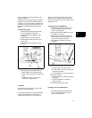
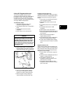
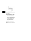
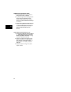
Test Interlock Switch Wiring
1. Disconnect interlock switch wires from
spade terminals on switch and at starter
motor connection.
2. Set meter to Ohms position.
3. Connect one meter test lead to the end of
one wire connector and other test lead to
the opposite connector in the same wire
(Figure 37). Meter should read low or no
resistance.
Figure 37
4. Move the wire inside the connector. Meter
should not change value.
5. Replace or repair wiring if there is
intermittent or no continuity. Repeat for
each wire in the harness.
12 Volt DC Starter Motor
Model Series 120000, 150000, 200000,
210000, 280000, 310000, 330000
These starter motors were produced in three
sizes to provide different cranking speeds and
torque. The length of the motor housing
determines the output as noted in the following
procedures.
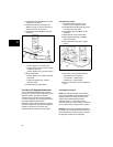
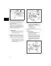
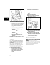
Check Starter Motor Drive and Clutch
When starter switch is activated, pinion gear
should rise, engage flywheel ring gear, and crank
engine. The pinion gear must rotate
counterclockwise, as viewed from gear. If starter
motor drive does not react properly, check helix
and pinion gear for free operation. If the pinion
gear sticks, clean the helix and gear with a mild
solvent and compressed air. If the pinion
continues to stick, replace the entire starter drive
assembly.
NOTE: Do not oil the pinion gear or clutch helix.
The starter motor clutch is designed to prevent
damage from shock loads such as engine
backfire. If clutch slips while cranking, replace
the entire starter drive assembly.
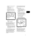
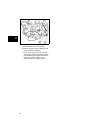
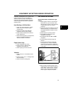
Test Starter Motor
1. Clamp starter motor test fixture in vise.
2. Remove starter motor from engine and
mount to fixture.
NOTICE:
Do not clamp motor housing in a vise
or strike with a hammer. Starter motors contain
ceramic magnets that can be damaged if the
motor housing is hit, deformed, or dented.
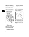
3. Set meter to DC Amps position.
4. Connect the optional starter switch
(A, Figure 38), starter motor, battery (F),
black lead (C), red lead (D), shunt (E), and
tachometer (B).