


37
2
2
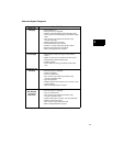
resistor is bypassed allowing full output to the
battery and clutch.
The battery is not used for the lights, so lights are
available even if the battery is disconnected or
removed. Current for the lights is available when
the engine is running. The output varies, so the
brightness of the lights changes with engine
speed.
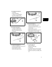
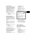
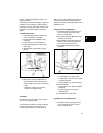
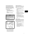
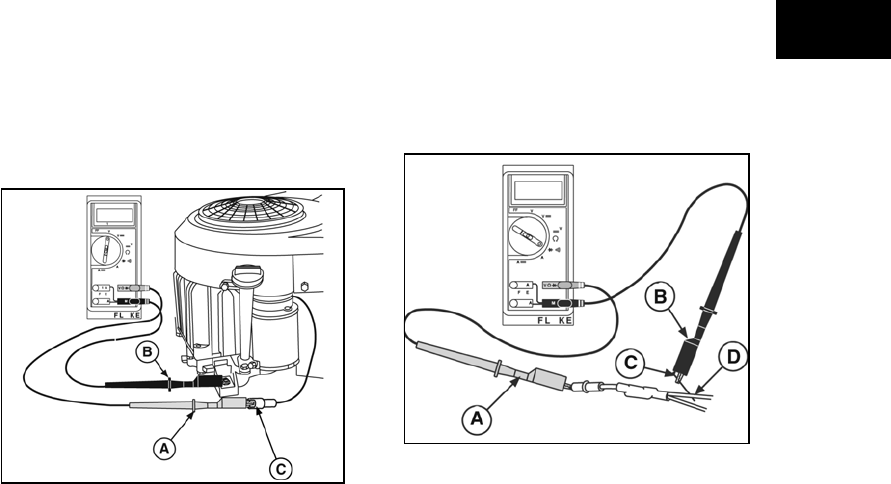
Test Alternator Output
1. Insert RED test lead (A, Figure 23) into
the V Ω receptacle in the meter.
2. Insert BLACK test lead (B) into COM
receptacle.
3. Rotate selector to AC Volts position.
4. Attach RED test lead clip to AC output
terminal (C).
5. Attach BLACK test lead clip to engine
ground.
Figure 23
6. With engine running at 3600 RPM, AC
output should be no less than 28 Volts.
• If NO or LOW output is found, replace the
stator.
• If alternator output is good, test the
diodes in the wiring harness.
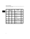
Test Diode
One diode is for the charging circuit, the other
diode is for the lighting circuit.
In the Diode Test position, the meter will display
forward voltage drop across the diode(s). If
voltage drop is less than 0.7 volts, meter will
“Beep” once as well as display voltage drop. A
continuous tone indicates continuity (shorted
diode). An incomplete circuit (open diode) will be
displayed as “OL.”
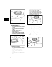
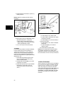
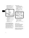
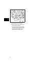
Charging Circuit Test (RED Wire)
1. Insert RED test lead (A, Figure 24) into
the V Ω receptacle and set the rotary
switch to Diode position.
2. Insert BLACK test lead (B) into the COM
receptacle in the meter.
3. Attach BLACK test lead clip to (C) of the
RED wire (D). (It may be necessary to
pierce wire with a pin as shown.)
4. Insert RED test lead (A) into harness
connector.
Figure 24
• If meter “Beeps” once, diode is OK.
• If meter makes a continuous tone, diode
is defective (shorted).
• If meter displays “OL,” proceed to Step 4.
5. Reverse test leads.
• If meter “Beeps” once, diode is installed
backwards.
• If meter still displays “OL,” diode is
defective (open).
6. If diode tests OK, replace stator.
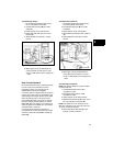
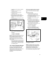
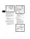
Lighting Circuit Test (WHITE Wire)
1. Insert RED test lead (A, Figure 25) into
the V Ω receptacle and set the rotary
switch to Diode position.