


145
10
10
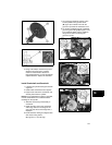
AVS® Balance System
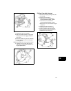
Remove
1. Remove blower housing, flywheel,
cylinder head, and sump. Discard gaskets.
2. Remove connecting rod and piston
assembly.
3. Remove crankshaft and counterweight
assembly.
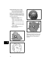
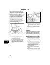
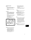
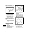
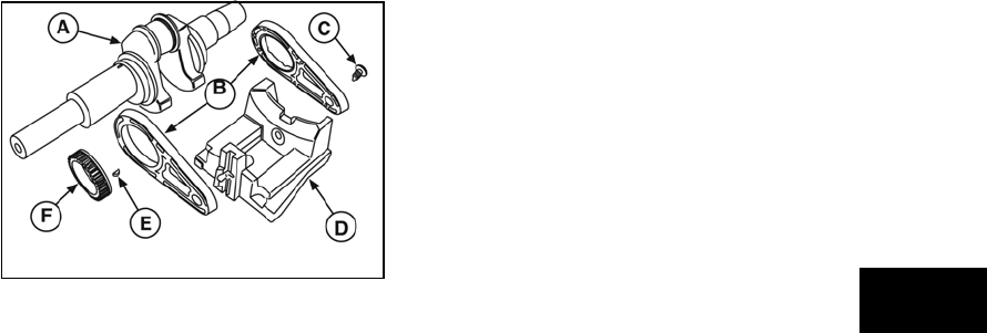
Disassemble
1. Remove the crankshaft gear (F, Figure
30) from the crankshaft (A). If the gear is
tight, pry it off using two screwdrivers,
being careful not to damage the gear.
2. The woodruff key (E) can be removed, if
required.
3. Remove and discard the plastic alignment
plug (C) from the magneto side of the
counterweight (D).
4. Slide the counterweight from the
counterweight links (B).
5. Remove PTO link and magneto link from
crankshaft.
Figure 30
Inspect
1. Visually inspect counterweight bearings
for scoring or discoloration. If found,
replace both counterweights as a set.
2. Measure the counterweight bearing
diameters and compare to the values
shown in Section 12 - Engine
Specifications. If either bearing is worn
beyond the reject dimensions, replace
both counterweights as a set.
3. Measure the crankshaft eccentric
diameters and compare to the values
shown in Section 12 - Engine
Specifications.
4. If crankshaft eccentrics are worn, scored,
or discolored, replace the crankshaft.
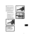
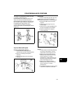
Assemble
1. Lubricate all bearing surfaces with clean
engine oil.
2. Slide the counterweight links on the
crankshaft eccentrics.
NOTICE: Both links must be installed with the
chamfered side facing the crankshaft crankpin.
3. Slide the counterweight into the
counterweight links.
4. Press a new plastic alignment plug into the
magneto side of the counterweight.
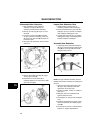
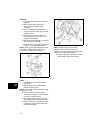
Install
1. Install the woodruff key to the crankshaft.
2. Install the timing gear to the crankshaft
with timing mark out. The flange of the
gear must face the counterweight link.
3. Place crankshaft and counterweight
assembly into the cylinder and start
magneto journal into magneto bearing.
4. Install connecting rod and piston.Torque
rod screws to values listed in Section 12 -
Engine Specifications.
NOTE: Lubrication hole in rod must face toward
magneto side.
5. Using new gaskets, install sump, cylinder
head, flywheel, and blower housing.