


70
4
4
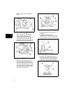
Inspect and Clean Carburetor Components
1. Inspect openings in the carburetor body
for evidence of wear or damage. If found,
replace the entire carburetor assembly.
2. Inspect the choke shaft, choke valve,
throttle shaft, and throttle valve for
evidence of wear or damage. Replace
parts as necessary.
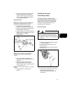
3. Using Carb/Choke Cleaner #100041 or
#100042, thoroughly clean the following
components, then follow with compressed
air to dry:
• Passages in the fixed main jet (bowl nut)
• Inside and outside of the fuel bowl
• Float
• Choke shaft and choke valve
• Throttle shaft and throttle valve
• All passages, openings, and the inside
and outside of the carburetor body
NOTE: Do not soak non-metallic components,
such as floats, o-rings, seals, or diaphragms, in
carb/choke cleaner or they will be damaged.
4. If any passages remain plugged after
cleaning, replace the component or the
entire carburetor assembly.
Assemble Carburetor
Consult the Illustrated Parts List to obtain the
appropriate carburetor overhaul kit before
reassembling the carburetor.
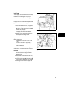
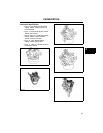
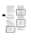
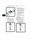
1. Install new Welch plug (A, Figure 17) with
a pin punch (B) of slightly smaller
diameter than the plug. Press against the
plug until it is flat in the carburetor
opening. Do not cave in the plug. Seal the
edge of the plug with a non-hardening
sealant.
Figure 17
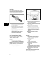
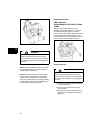
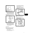
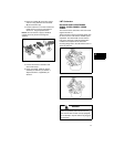
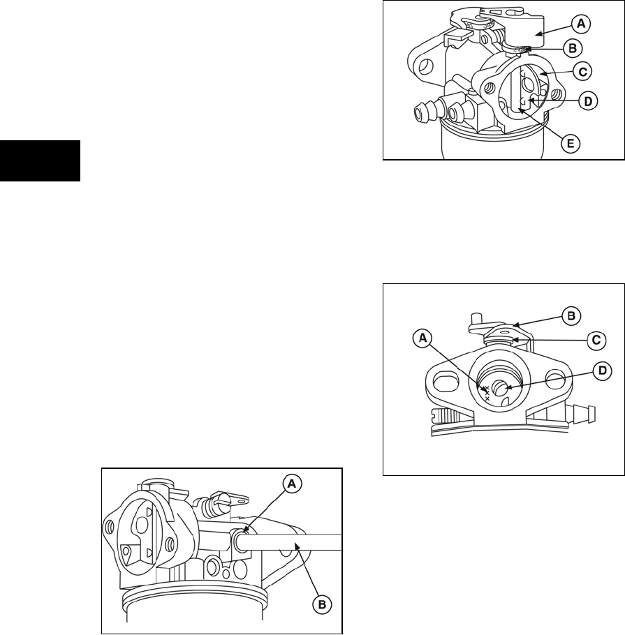
2. Install new foam seal (B, Figure 18) on
choke shaft (E), then slide shaft into
carburetor body (C). Rotate shaft
clockwise (A), and insert choke valve into
slot until centered, with dimples (D)
positioned as shown. Actuate the choke
shaft to check for proper movement.
Figure 18
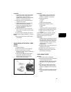
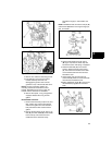
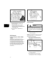
3. Install new foam seal (C, Figure 19) on
throttle shaft (B), then slide shaft into
carburetor body. Rotate shaft until flat is
facing out. Position throttle valve on flat
with numbers facing out (A), then install
screws (D). Actuate the throttle shaft to
check for proper movement.
Figure 19
4. Install idle speed screw and spring. Install
idle mixture screw and spring with a new
limiter cap, if equipped.
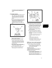
5. Using Bushing Driver #19057
(A, Figure 20), install new needle seat with
grooved edge down (B) until firmly seated.