


148
9
11
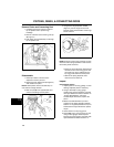
PISTONS, RINGS, & CONNECTING RODS
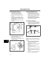
Remove Piston and Connecting Rod
1. Carefully remove any carbon or ridge at
top of cylinder bore to prevent ring
breakage.
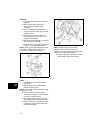
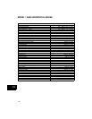
2. Remove rod bolts and connecting rod cap
(A, Figure 1).
3. Push piston and rod assembly out through
top of cylinder bore.
Figure 1
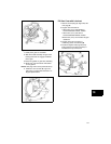
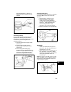
Disassemble
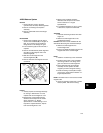
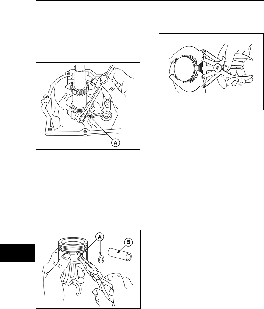
1. Rotate pin retainer until one end is
exposed in notch in pin bore.
2. Remove the two retainer pins (A, Figure 2)
with needle nose pliers.
NOTE: Some pistons have a shoulder stop on
one side and a single retainer.
3. Slide out pin (B) from opposite side and
remove connecting rod from piston.
Figure 2
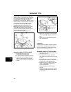
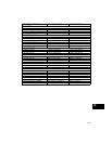
4. Using Piston Ring Expander #19340
(Figure 3), remove rings one at a time.
Note the order and orientation of the rings
before removal.
Figure 3
NOTE: Some oil control rings consist of two thin
steel rails and a spring expander. These must be
removed by hand as follows:
• Grasp one end of the upper steel rail and
wind the rail from the oil ring groove into
the center ring groove. Repeat into the
top ring groove and then off the piston.
• Remove the spring expander, then
remove the lower steel rail.
Inspect
Check Piston and Pin
1. Inspect piston for scoring, galling, or other
damage. Replace piston if necessary.
2. Using a dial caliper or plug gauge,
measure the pin bore diameter. Compare
with reject dimensions listed in Section 12
- Engine Specifications. If pin bore
exceeds reject dimensions, replace the
piston.
3. Measure outside diameter of pin and
compare to the reject dimension listed in
Section 12 - Engine Specifications. If pin is
smaller that the reject dimension, replace
the pin.
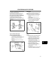
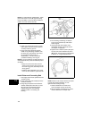
4. Clean carbon from top ring groove.
5. Place NEW ring in groove (Figure 4) and,
using a feeler gauge, measure space
between ring and ring land. Compare with
reject dimensions listed in Section 12 -