


43
2
2
ELECTRIC STARTERS
Before assuming an electric starter requires
service, check the engine for freedom of rotation
by removing the spark plug and turning the
crankshaft over by hand. Any belt, clutch, or
other parasitic load will affect the starter cranking
performance, so ensure their effects are
minimized.
The following list is given to aid in diagnosing
problems for 12 Volt and 120 Volt starting
systems.
1. Engine Cranks Slowly
• Parasitic load affecting performance
• Discharged, defective, or incorrect
battery (also, see alternators)
• Faulty electrical connection (battery
circuit)
• Dirty or worn starter motor commutator,
bearing, weak magnets, etc.
• Wrong engine oil viscosity for ambient
temperatures
• Defective starter clutch
• Band brake misadjusted
• Battery leads too long or wire diameter
too small
• Extension cord longer than 25 feet (7.60
mm) (120 volt AC only)
2. Engine Will Not Crank
• Faulty safety interlocks
• Discharged or defective battery
• Faulty electrical connections
• Faulty starter motor switch (open circuit)
• Open circuit in starter motor
• Defective rectifier assembly (120 Volt AC
only)
• Brushes sticking, etc.
• Faulty solenoid
• Blown fuse or tripped breaker at power
source.
3. Starter Motor Spins But Does Not Crank
Engine
• Sticking pinion gear
• Damaged pinion or ring gear
• Starter motor clutch slipping
• Incorrect rotation due to reversed motor
polarity (all motors rotate
counterclockwise, as viewed from pinion
gear)
4. Starter Motor Blows Fuses - (120 Volt
Starter Motor Only)
• Parasitic load
• Shorted rectifier assembly
• Shorted 120 volt extension cord to starter
motor
• Armature shorted
• Overloaded circuit
5. Starter Motor Spins But Will Not Stop
• Defective starter switch
• Defective solenoid
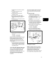
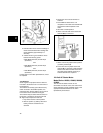
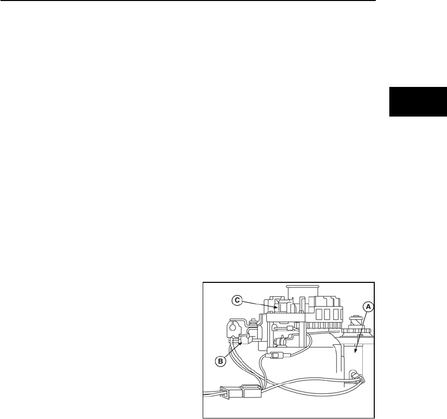
SYSTEM 3®, SYSTEM 4®
Model Series 97700, 99700, 110000,
120000
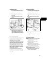
Both of these systems consist of a starter motor
(A, Figure 33), starter switch, interlock switch (B),
and solenoid (optional). When the starter switch
or solenoid is actuated, the battery supplies
power to the starter motor, cranking the engine.
When the engine is running, the alternator (C)
recharges the battery.
Figure 33
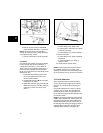
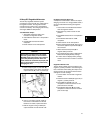
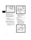
Check Starter Motor Drive and Clutch
When starter switch is activated, pinion gear
(A, Figure 34) should rise, engage flywheel ring
gear, and crank engine. The pinion gear must
rotate counterclockwise, as viewed from gear.
If starter motor drive does not react properly,
check helix (B) and pinion gear for free
operation.