


15
breaker requirements and disconnect switch size and
location. Route 125--v power supply conductors into the
bottom of the utility box containing the duplex receptacle.
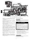
Unit--powered type: A unit--mounted transformer is
factory--installed to stepdown the main power supply
voltage to the unit to 115--v at the duplex receptacle. This
option also includes a manual switch with fuse, located in
a utility box and mounted on a bracket behind the
convenience outlet; access is through the unit’s control
box access panel. See Fig. 14.
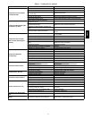
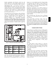
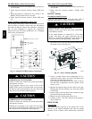
The primary leads to the convenience outlet transformer
are not factory--connected. Selection of primary power
source is a customer--option. If local codes permit, the
transformer primary leads can be connected at the
line--side terminals on a unit--mounted non--fused
disconnect or HACR breaker switch; this will provide
service power to the unit when the unit disconnect switch
or HACR switch is open. Other connection methods will
result in the convenience outlet circuit being de--energized
when the unit disconnect or HACR switch is open. See
Fig. 15.
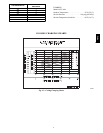
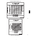
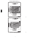
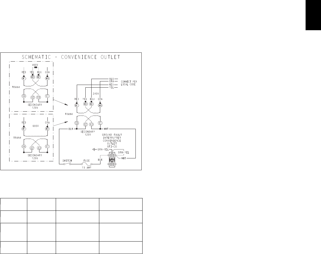
CO8283
Fig. 15 -- Powered Convenience Outlet Wiri ng
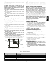
UNIT
VOLTAGE
CONNECT
AS
PRIMARY
CONNECTIONS
TRANSFORMER
TERMINALS
208,
230
240
L1: RED +YEL
L2: BLU + GRA
H1 + H3
H2 + H4
460 480
L1: RED
Splice BLU + YEL
L2: GRA
H1
H2 + H3
H4
575 600
L1: RED
L2: GRA
H1
H2
Duty Cycle: The unit--powered convenience outlet has a
duty cycle limitation. The transformer is intended to
provide power on an intermittent basis for service tools,
lamps, etc; it is not intended to provide 15--amps loading
for continuous duty loads (such as electric heaters for
overnight use). Observe a 50% limit on circuit loading
above 8--amps (i.e., limit loads exceeding 8--amps to 30
minutes of operation every hour).
Maintenance: Periodically test the GFCI receptacle by
pressing the TEST button on the face of the receptacle.
This should cause the internal circuit of the receptacle to
trip and open the receptacle. Check for proper grounding
wires and power line phasing if the GFCI receptacle does
not trip as required. Press the RESET button to clear the
tripped condition.
Fuse on powered type: The factory fuse is a Bussman
“Fusetron” T--15, non--renewable screw--in (Edison base)
type plug fuse.
Using unit--mounted convenience outlets: Units with
unit--mounted convenience outlet circuits will often
require that two disconnects be opened to de--energize all
power to the unit. Treat all units as electrically energized
until the convenience outlet power is also checked and
de--energization is confirmed. Observe National Electrical
Code Article 210, Branch Circuits, for use of convenience
outlets.
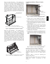
SMOKE DETECTORS
Smoke detectors are available as factory--installed options
on 48TC models. Smoke detectors may be specified for
Supply Air only or for Return Air without or with
economizer or in combination of Supply Air and Return
Air. Return Air smoke detectors are arranged for vertical
return configurations only. All components necessary for
operation are factory--provided and mounted. The unit is
factory--configured for immediate smoke detector
shutdown operation; additional wiring or modifications to
unit terminal board may be necessary to complete the unit
and smoke detector configuration to meet project
requirements.
System
The smoke detector system consists of a four--wire
controller and one or two sensors. Its primary function is
to shut down the rooftop unit in order to prevent smoke
from circulating throughout the building. It is not to be
used as a life saving device.
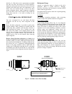
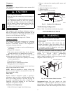
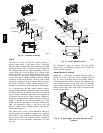
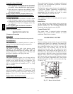
Controller
The controller (see Fig. 16) includes a controller housing,
a printed circuit board, and a clear plastic cover. The
controller can be connected to one or two compatible duct
smoke sensors. The clear plastic cover is secured to the
housing with a single captive screw for easy access to the
wiring terminals. The controller has three LEDs (for
Power, Trouble and Alarm) and a manual test/reset button
(on the cover face).
48TC