


4
C07156
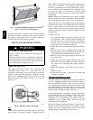
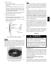
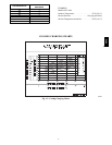
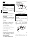
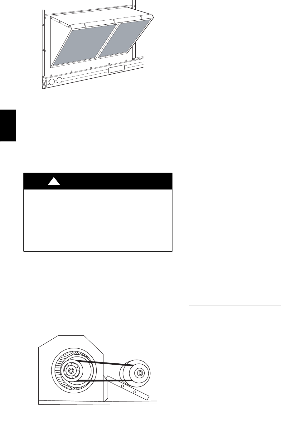
Fig. 4 -- Screens Installed on Outdoor--Air Hood
(Sizes 7--1/2 to 12-- 1/2 Tons Shown)
To remove the screen, loosen the screws in the top retainer
and slip the retainer up until the filter can be removed.
Re--install by placing the frame in its track, rotating the
retainer back down and tighten all screws.
SUPPLY FAN (BLOWER) SECTION
ELECTRICAL SHOCK HAZARD
Failure to follow this warning could cause personal
injury or death.
Before performing service or maintenance operations
on the fan system, shut off all unit power and tag--out
the unit disconnect switch. Do not reach into the fan
section with power still applied to unit.
!
WARNING
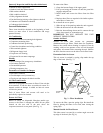
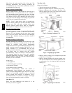
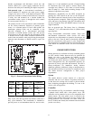
Supply Fan (Belt-- Drive)
The supply fan system consists of a forward--curved
centrifugal blower wheel on a solid shaft with two
concentric type bearings, one on each side of the blower
housing. A fixed--pitch driven pulley is attached to the fan
shaft and an adjustable--pitch driver pulley is on the
motor. The pulleys are connected using a “V” type belt.
(See Fig. 5.)
C07087
Fig. 5 -- Belt Drive Motor Mounting
Belt
Check the belt condition and tension quarterly. Inspect the
belt for signs of cracking, fraying or glazing along the
inside surfaces. Check belt tension by using a spring--force
tool (such as Browning’s Part Number “Belt Tension
Checker” or equivalent tool); tension should be 6--lbs at a
5/8--in. deflection when measured at the centerline of the
belt span. This point is at the center of the belt when
measuring the distance between the motor shaft and the
blower shaft.
NOTE: Without the spring--tension tool, place a straight
edge across the belt surface at the pulleys, then deflect the
belt at mid--span using one finger to a 1/2--in. deflection.
Adjust belt tension by loosening the motor mounting plate
front bolts and rear bolt and sliding the plate toward the
fan (to reduce tension) or away from fan (to increase
tension). Ensure the blower shaft and the motor shaft are
parallel to each other (pulleys aligned). Tighten all bolts
when finished.
To replace the belt:
1. Use a belt with same section type or similar size. Do
not substitute a “FHP” type belt. When installing the
new belt, do not use a tool (screwdriver or pry--bar) to
force the belt over the pulley flanges, this will stress
the belt and cause a reduction in belt life.
2. Loosen the motor mounting plate front bolts and rear
bolts.
3. Push the motor and its mounting plate towards the
blower housing as close as possible to reduce the cen-
ter distance between fan shaft and motor shaft.
4. Remove the belt by gently lifting the old belt over
one of the pulleys.
5. Install the new belt by gently sliding the belt over
both pulleys and then sliding the motor and plate
away from the fan housing until proper tension is
achieved.
6. Check the alignment of the pulleys, adjust if neces-
sary.
7. Tighten all bolts.
8. Check the tension after a few hours of runtime and
re--adjust as required.
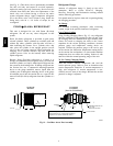
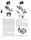
Adjustable--Pitch Pulley on
Motor
The motor pulley is an adjustable--pitch type that allows a
servicer to implement changes in the fan wheel speed to
match as--installed ductwork systems. The pulley consists
of a fixed flange side that faces the motor (secured to the
motor shaft) and a movable flange side that can be rotated
around the fixed flange side that increases or reduces the
pitch diameter of this driver pulley. (See Fig. 6.)
As the pitch diameter is changed by adjusting the position
of the movable flange, the centerline on this pulley shifts
laterally (along the motor shaft). This creates a
requirement for a realignment of the pulleys after any
adjustment of the movable flange. Also reset the belt
tension after each realignment.
Check the condition of the motor pulley for signs of wear.
Glazing of the belt contact surfaces and erosion on these
surfaces are signs of improper belt tension and/or belt
slippage. Pulley replacement may be necessary.
48TC