


33
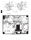
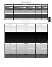
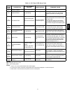
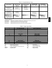
Table 14 – IGC Board LED Alarm Codes
LED
FLASH
CODE
DESCRIPTION
ACTION T AKEN BY
CONTROL
RESET METHOD PROBABLE CAUSE
On Normal Operation — — —
Off Hardware Failure No gas heating. —
Loss of power to the IGC. Check 5 amp
fuse on IGC, power to unit, 24V circuit
breaker, transformer, and wiring to the
IGC.
2
Flashes
Limit Switch Fault
Gas valve and igniter
Off.
Indoor fan and inducer
On.
Limit switch closed,
or heat call (W) Off.
High temperature limit switch is open.
Check the operation of the indoor (evapo-
rator) fan motor.
Ensure that the supply-air temperature
rise is within the range on the unit name-
plate. Check wiring and limit switch opera-
tion.
3
Flashes
Flame Sense Fault
Indoor fan and inducer
On.
Flame sense normal.
P o wer reset for LED
reset.
The IGC sensed a flame when the gas
valve should be closed. Check wiring,
flame sensor, and gas valve operation.
4
Flashes
Four Consecutive Limit
Switch Fault
No gas heating.
Heat call (W) Off.
P o wer reset for LED
reset.
4 consecutive limit switch faults within a
single call for heat. See Limit Switch Fault.
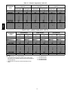
5
Flashes
Ignition Fault No gas heating.
Heat call (W) Off.
P o wer reset for LED
reset.
Unit unsuccessfully attempted ignition for
15 minutes. Check igniter and flame sen-
sor electrode spacing, gaps, etc. Check
flame sense and igniter wiring. Check gas
valve operation and gas supply. Check
gas valve connect ions to IGC terminals.
BRN l ead must be on Pin 11.
6
Flashes
Induced Draft Motor
Fault
If heat off: no gas
heating.
If heat on: gas valve
Off and inducer On.
Inducer sense nor-
mal, or heat call (W)
Off.
Inducer sense On when heat call Off, or
inducer sense Off when heat call On.
Check wiring, voltage, and o peration of
IGC motor. Check speed sensor wiring to
IGC.
7
Flashes
Rollout Switch Lockout
Gas valve and igniter
Off.
Indoor fan and inducer
On.
Po wer reset.
Rollout switch has opened. Check gas
valve operation. Check induced-draft
blower wheel is properly secured to motor
shaft.
8
Flashes
Internal Control Lockout No gas heating. Power reset.
IGC has sensed internal hardware or soft-
ware error. If fault is not cleared by reset-
ting 24 v power, replace the IGC.
9
Flashes
Temporary Software
Lockout
No gas heating.
1 hour auto reset, or
power reset.
Electrical interference is disrupting the
IGC software.
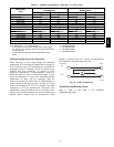
LEGEND
IGC --- Integrated Gas Unit Control
LED --- Lig ht --- Emitting Diode
NOTES:
1. There is a 3---second pause between alarm code displays.
2. If more than one alarm code exists, all applicable alarm codes will be displayed in numerical sequence.
3. Alarm codes on the IGC will be lost if power to the unit is interrupted.
48TC