


63
Single Enthalpy
To check single enthalpy:
1. Make sure EconoMi$er IV preparation procedure has
been performed.
2. Set the enthalpy potentiometer to A (fully CCW). The
Free Cool LED should be lit.
3. Set the enthalpy potentiometer to D (fully CW). The
Free Cool LED should turn off.
4. Return EconoMi$er IV settings and wiring to normal
after completing troubleshooting.
DCV (Demand Controlled Ventilation) and
Power
Exhaust
To check DCV and Power Exhaust:
1. Make sure EconoMi$er IV preparation procedure has
been performed.
2. Ensure terminals AQ and AQ1 are open. The LED for
both DCV and Exhaust should be off. The actuator
should be fully closed.
3. Connect a 9--v battery to AQ (positive node) and AQ1
(negative node). The LED for both DCV and Exhaust
should turn on. The actuator should drive to between
90 and 95% open.
4. Turn the Exhaust potentiometer CW until the Exhaust
LED turns off. The LED should turn off when the po-
tentiometer is approximately 90%. The actuator
should remain in position.
5. Turn the DCV setpoint potentiometer CW until the
DCV LED turns off. The DCV LED should turn off
when the potentiometer is approximately 9--v. The ac-
tuator should drive fully closed.
6. Turn the DCV and Exhaust potentiometers CCW until
the Exhaust LED turns on. The exhaust contacts will
close 30 to 120 seconds after the Exhaust LED turns
on.
7. Return EconoMi$er IV settings and wiring to normal
after completing troubleshooting.
DCV Minimum and Maximum
Position
To check the DCV minimum and maximum position:
1. Make sure EconoMi$er IV preparation procedure has
been performed.
2. Connect a 9--v battery to AQ (positive node) and AQ1
(negative node). The DCV LED should turn on. The
actuator should drive to between 90 and 95% open.
3. Turn the DCV Maximum Position potentiometer to
midpoint. The actuator should drive to between 20
and 80% open.
4. Turn the DCV Maximum Position potentiometer to
fully CCW. The actuator should drive fully closed.
5. Turn the Minimum Position potentiometer to mid-
point. The actuator should drive to between 20 and
80% open.
6. Turn the Minimum Position Potentiometer fully CW.
The actuator should drive fully open.
7. Remove the jumper from TR and N. The actuator
should drive fully closed.
8. Return EconoMi$er IV settings and wiring to normal
after completing troubleshooting.
Supply--Air Sensor
Input
To check supply--air sensor input:
1. Make sure EconoMi$er IV preparation procedure has
been performed.
2. Set the Enthalpy potentiometer to A. The Free Cool
LED turns on. The actuator should drive to between
20 and 80% open.
3. Remove the 5.6 kilo--ohm resistor and jumper T to
T1. The actuator should drive fully open.
4. Remove the jumper across T and T1. The actuator
should drive fully closed.
5. Return EconoMi$er IV settings and wiring to normal
after completing troubleshooting.
EconoMi$e r IV Troubleshooting
Completion
This procedure is used to return the EconoMi$er IV to
operation. No troubleshooting or testing is done by
performing the following procedure.
1. Disconnect power at TR and TR1.
2. Set enthalpy potentiometer to previous setting.
3. Set DCV maximum position potentiometer to previ-
ous setting.
4. Set minimum position, DCV setpoint, and exhaust po-
tentiometers to previous settings.
5. Remove 620--ohm resistor from terminals SR and +.
6. Remove 1.2 kilo--ohm checkout resistor from termin-
als SO and +. If used, reconnect sensor from termin-
als SO and +.
7. Remove jumper from TR to N.
8. Remove jumper from TR to 1.
9. Remove 5.6 kilo--ohm resistor from T and T1. Recon-
nect wires at T and T1.
10. Remove jumper from P to P1. Reconnect device at P
and P1.
11. Apply power (24 vac) to terminals TR and TR1.
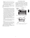
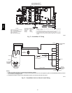
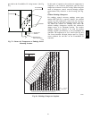
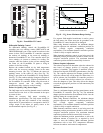
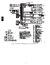
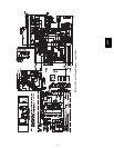
WIRING DIAGRAMS
See Fig. 83 and Fig. 84 for typical wiring diagrams.
48TC