


42
At any baud (9600, 19200, 38400 baud), the number of
controllers is limited to 239 devices maximum. Bus length
may not exceed 4000 ft, with no more than 60 total
devices on any 1000--ft section. Optically isolated RS--485
repeaters are required every 1000 ft.
NOTE: Carrier device default is 9600 band.
COMMUNICATION BUS WIRE SPECIFICATIONS —
The CCN Communication Bus wiring is field--supplied
and field--installed. It consists of shielded 3--conductor
cable with drain (ground) wire. The cable selected must
be identical to the CCN Communication Bus wire used for
the entire network.
See Table 19 for recommended cable.
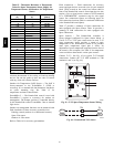
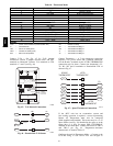
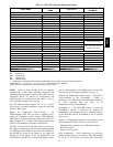
Table 19 – Recommended Cables
MANUF ACTURER CABLE PART NO.
Alpha 2413 or 5463
American A22503
Belden 8772
Columbia 02525
NOTE: Conductors and drain wire must be at least 20
AWG, stranded, and tinned copper. Individual conductors
must be insulated with PVC, PVC/nylon, vinyl, Teflon, or
polyethylene. An aluminum/polyester 100% foil shield
and an outer jacket of PVC, PVC/nylon, chrome vinyl, or
Teflon with a minimum operating temperature range of
--20 C to 60 C is required. Do not run communication wire
in the same conduit as or next to any AC voltage wiring.
The communication bus shields must be tied together at
each system element. If the communication bus is entirely
within one building, the resulting continuous shield must
be connected to ground at only one single point. If the
communication bus cable exits from one building and
enters another building, the shields must be connected to
the grounds at a lightning suppressor in each building (one
point only).
Connecting CCN bus:
NOTE: When connecting the communication bus cable,
a color code system for the entire network is
recommended to simplify installation and checkout. See
Table 20 for the recommended color code.
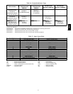
Table 20 – Color Code Recommendations
SIGNAL TYPE
CCN BUS WIRE
COLOR
CCN PLUG PIN
NUMBER
+ Red 1
Ground White 2
--- Black 3
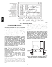
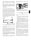
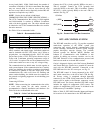
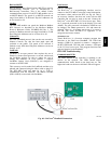
Connect the CCN (+) lead (typically RED) to the units
TB1--12 terminal. Connect the CCN (ground) lead
(typically WHT) to the unit’s TB1--14 terminal. Connect
the CCN (--) lead (typically BLK) to the unit’s TB1--16
terminal. See Fig. 58.
CCN Bus
J2-1
J2-2
GND (WHT)
12
14
TB1
J2-3
– (BLK)
16
TB1
TB1
PL
+ (RED)
C08276
Fig. 58 -- PremierLink CCN Bus Connections
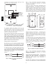
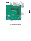
RTU--MP CONTROL SYSTEM
The RTU--MP controller, see Fig. 59, provides expanded
stand--alone operation of the HVAC system plus
connection and control through communication with
several Building Automation Systems (BAS) through
popular third--party network systems. The available
network systems are BACnet MP/TP, Modbus and
Johnson J2. Communication with LonWorks is also
possible by adding an accessory interface card to the
RTU--MP. Selection of the communication protocol and
baud rate are made at on--board DIP switches.
Carrier’s diagnostic display tools BACviewer6 Handheld
and Virtual BACview (loaded on a portable PC) must be
used with the RTU--MP controller. Connection to the
RTU--MP board is at the J12 access port, see Fig. 59.
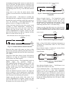
The RTU--MP control is factory--mounted in the 48TC
unit’s main control box, to the left of the LCTB. See Fig.
60. Factory wiring is completed through harnesses
connected to the LCTB. Field connections for RTU--MP
sensors will be made at the Phoenix connectors on the
RTU--MP board. The factory--installed RTU--MP control
includes the supply--air temperature (SAT) sensor. The
outdoor air temperature (OAT) sensor is included in the
FIOP/accessory EconoMi$er 2 package.
Refer to Table 21, RTU--MP Controller Inputs and Outputs
for locations of all connections to the RTU--MP board.
48TC