


25
Burners and Igniters
EQUIPMENT DAMAGE HAZARD
Failure to follow this caution may result in
equipment damage.
When working on gas train, do not hit or plug
orifice spuds.
CAUTION
!
Main Burners
To access burners, remove burner access panel and slide
out burner partition. At the beginning of each heating
season, inspect for deterioration or blockage due to
corrosion or other causes. Observe the main burner flames
and adjust, if necessary.
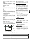
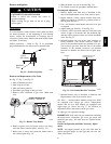
Orifice projection — Refer to Fig. 32 for maximum
projection dimension for orifice face to manifold tube.
Orifice
1.00-in
(25.4 mm)
Manifold
Pipe
C08211
Fig. 32 -- Orifice Projection
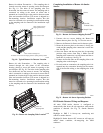
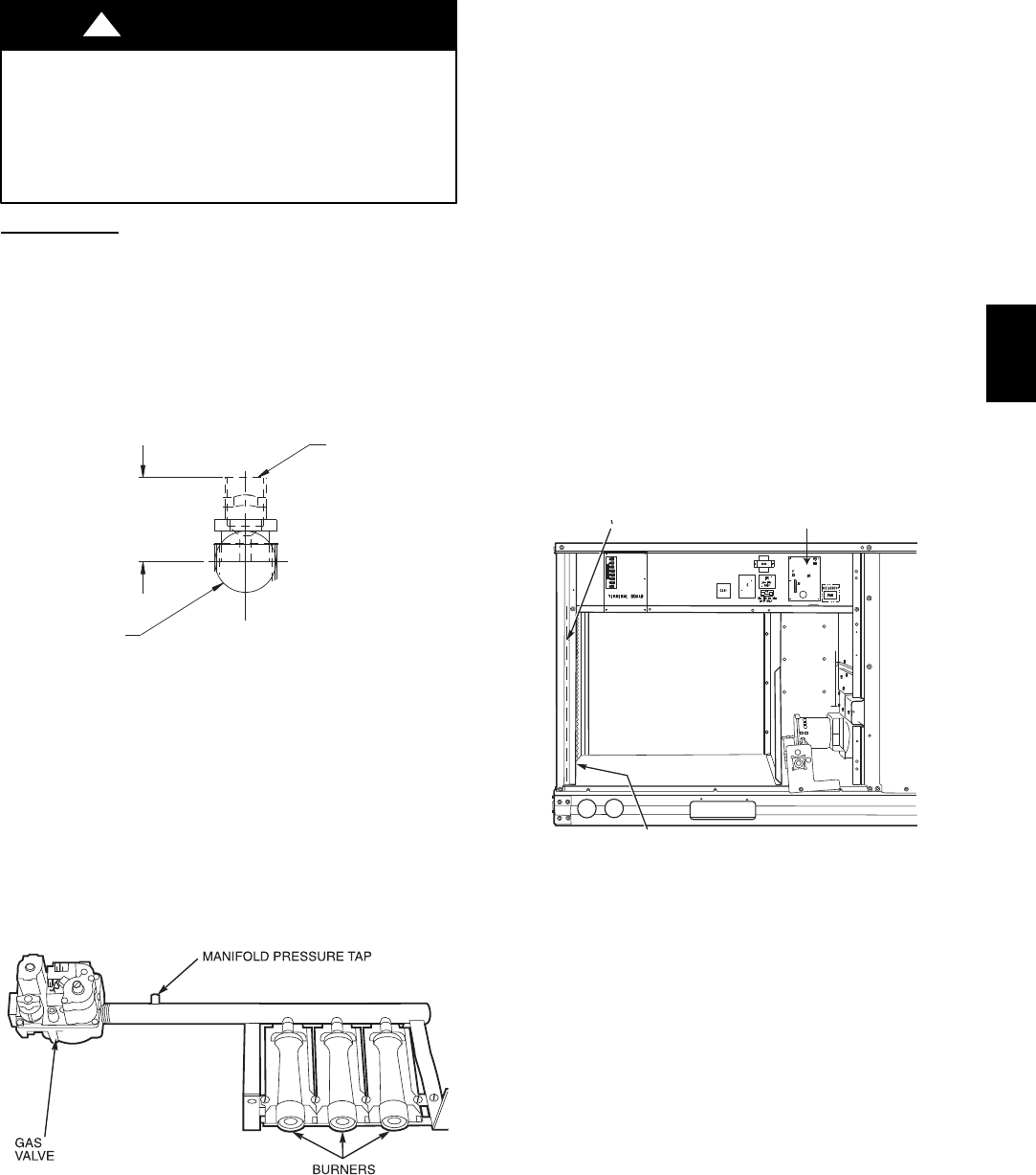
Removal and Replacement of Gas Train
See Fig. 27, Fig. 31 and Fig. 33.
1. Shut off manual gas valve.
2. Shut off power to unit.
3. Slide out burner partition.
4. Disconnect gas piping at unit gas valve.
5. Remove wires connected to gas valve. Mark each
wire.
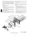
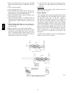
C06153
Fig. 33 -- Burner Tray Details
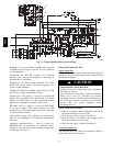
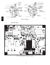
6. Remove igniter wires and sensor wires at the Integ-
rated Gas Unit Controller (IGC). (See Fig. 34.)
7. Remove the 2 screws that attach the burner rack to
the vestibule plate (Fig. 31).
8. Slide the burner tray out of the unit (Fig. 33).
9. To reinstall, reverse the procedure outlined above.
Cleaning and Adjustment
1. Remove burner rack from unit as described in Re-
moval and Replacement of Gas Train section, above.
2. Inspect burners; if dirty, remove burners from rack.
(Mark each burner to identify its position before re-
moving from the rack.)
3. Use a soft brush to clean burners and cross--over port
as required.
4. Adjust spark gap. (See Fig. 35 and Fig. 36.)
5. If factory orifice has been removed, check that each
orifice is tight at its threads into the manifold pipe
and that orifice projection does not exceed maximum
valve. See Fig. 32
6. Reinstall burners on rack in the same locations as
factory--installed. (The outside crossover flame re-
gions of the outermost burners are pinched off to pre-
vent excessive gas flow from the side of the burner
assembly. If the pinched crossovers are installed
between two burners, the flame will not ignite prop-
erly.)
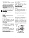
RACEWAY
INTEGRATED GAS UNIT
CONTROLLER (IGC)
HOLE IN END PANEL (HIDDEN)
C08454
Fig. 34 -- Unit Control Box/IGC Location
7. Reinstall burner rack as described in Removal and
Replacement of Gas Train section, above.
Gas Valve — All three--phase models (except Low NO
x
)
are equipped with 2--stage gas valves. Single--phase
models and all Low NO
x
models are equipped with
single--stage gas valves. See Fig. 37 for locations of
adjustment screws and features on the gas valves.
To adjust gas valve pressure settings:
IMPORTANT: Leak check all gas connections including
the main service connection, gas valve, gas spuds, and
manifold pipe plug. All leaks must be repaired before
firing unit.
Check Unit Operation and Make Necessary Adjust-
ments
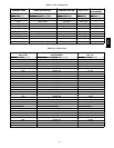
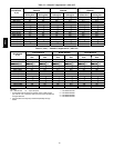
NOTE: Gas supply pressure at gas valve inlet must be
within specified ranges for fuel type and unit size. See
Table 4 and Table 5.
48TC