


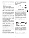
46
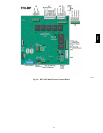
connects to the RTU--MP must be routed through the
raceway built into the corner post as shown in Fig. 34.
The raceway provides the UL required clearance between
high-- and low--voltage wiring. Pass the control wires
through the hole provided in the corner post, then feed the
wires thorough the raceway to the RTU--MP. Connect to
the wires to the removable Phoenix connectors and then
reconnect the connectors to the board.
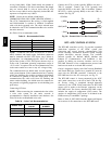
Space Temperatur e (SPT) Sensors
A field--supplied Carrier space temperature sensor is
required with the RTU--MP to monitor space temperature.
There are 3 sensors available for this application:
S 33ZCT55SPT, space temperature sensor with override
button
S 33ZCT56SPT, space temperature sensor with override
button and setpoint adjustment
S 33ZCT59SPT, space temperature sensor with LCD
(liquid crystal display) screen, override button, and
setpoint adjustment
Use 20 gauge wire to connect the sensor to the controller.
The wire is suitable for distances of up to 500 ft. Use a
three--conductor shielded cable for the sensor and setpoint
adjustment connections. If the setpoint adjustment
(slidebar) is not required, then an unshielded, 18 or 20
gauge, two--conductor, twisted pair cable may be used.
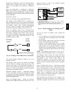
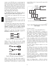
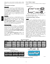
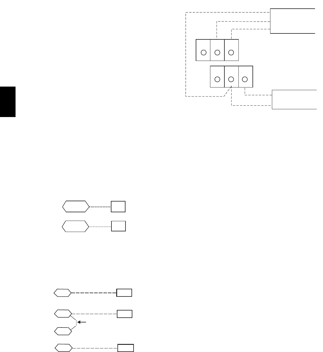
Connect T--55 -- See Fig. 43 for typical T--55 internal
connections. Connect the T--55 SEN terminals to
RTU--MP J20--1 and J20--2. See Fig. 61.
SEN
SEN
J20-1
J20-2
C08460
Fig. 61 -- RTU--MP T--55 Sensor Connections
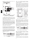
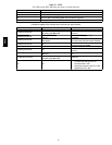
Connect T--56 -- See Fig. 45 for T--56 internal
connections. Install a jumper between SEN and SET
terminals as illustrated. Connect T--56 terminals to
RTU--MP J20--1, J20--2 and J20--3 per Fig. 62.
SEN J20-1
J20-2
SEN
SET
Jumper
J20-3
SET
C08461
Fig. 62 -- RTU--MP T--56 Sensor Connections
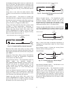
Connect T--59 -- The T--59 space sensor requires a
separate, isolated power supply of 24 VAC. See Fig. 61
for internal connections at the T--59. Connect the SEN
terminal (BLU) to RTU--MP J20--1. Connect the COM
terminal (BRN) to J20--2. Connect the SET terminal (STO
or BLK) to J20--3.
OR SET SEN
OPB COM- PWR+
BLU (SPT)
BLK (STO)
24 VAC
SENSOR
WIRING
POWER
WIRING
BRN (COM)
NOTE: Must use a separate isolated transformer.
C07132
Fig. 63 -- Space Temperature Sensor Typical Wiring
(33ZCT59SPT)
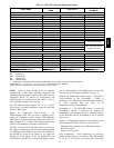
Economizer controls —
Outdoor Air Enthalpy Control (PNO HH57AC077) --
The enthalpy control (HH57AC077) is available as a
field--installed accessory to be used with the EconoMi$er2
damper system. The outdoor air enthalpy sensor is part of
the enthalpy control. (The separate field--installed
accessory return air enthalpy sensor (HH57AC078) is
required for differential enthalpy control. See below.)
Locate the enthalpy control in the economizer hood.
Locate two GRA leads in the factory harness and connect
these leads to enthalpy control sensors 2 and 3. See Fig.
48. Connect the enthalpy control power input terminals to
economizer actuator power leads RED (connect to TR)
and BLK (connect to TR1).
The outdoor enthalpy changeover setpoint is set at the
enthalpy controller.
The enthalpy control receives the outdoor air enthalpy
from the outdoor air enthalpy sensor and provides a dry
contact switch input to the RTU--MP controller. A closed
contact indicates that outside air is preferred to the return
air. An open contact indicates that the economizer should
remain at minimum position.
Differential Enthalpy Control — Differential enthalpy
control is provided by sensing and comparing the outside
air and return air enthalpy conditions. Install the outdoor
air enthalpy control as described above. Add and install a
return air enthalpy sensor.
Return Air Enthalpy Sensor — Mount the return--air
enthalpy sensor (HH57AC078) in the return--air duct. The
48TC