


59
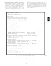
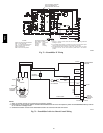
provided in the EconoMi$er IV wiring harness. (See Fig.
70.)
ECONOMI$ERIV
ECONOMI$ERIV
CONTROLLER
GROMMET
RETURN AIR
SENSOR
RETURN DUCT
(FIELD-PROVIDED)
C07085
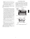
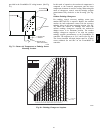
Fig. 79 -- Return Air Temperature or Enthalpy Sensor
Mounting Location
In this mode of operation, the outdoor-air temperature is
compared to the return-air temperature and the lower
temperature airstream is used for cooling. When using this
mode of changeover control, turn the enthalpy setpoint
potentiometer fully clockwise to the D setting. (See Fig.
76.)
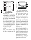
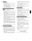
Outdoor Enthalpy Changeover
For enthalpy control, accessory enthalpy sensor (part
number HH57AC078) is required. Replace the standard
outdoor dry bulb temperature sensor with the accessory
enthalpy sensor in the same mounting location. (See Fig.
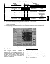
79.) When the outdoor air enthalpy rises above the
outdoor enthalpy changeover setpoint, the outdoor-air
damper moves to its minimum position. The outdoor
enthalpy changeover setpoint is set with the outdoor
enthalpy setpoint potentiometer on the EconoMi$er IV
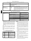
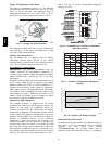
controller. The setpoints are A, B, C, and D. (See Fig. 80.)
The factory-installed 620-ohm jumper must be in place
across terminals S
R
and SR+ on the EconoMi$er IV
controller.
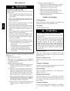
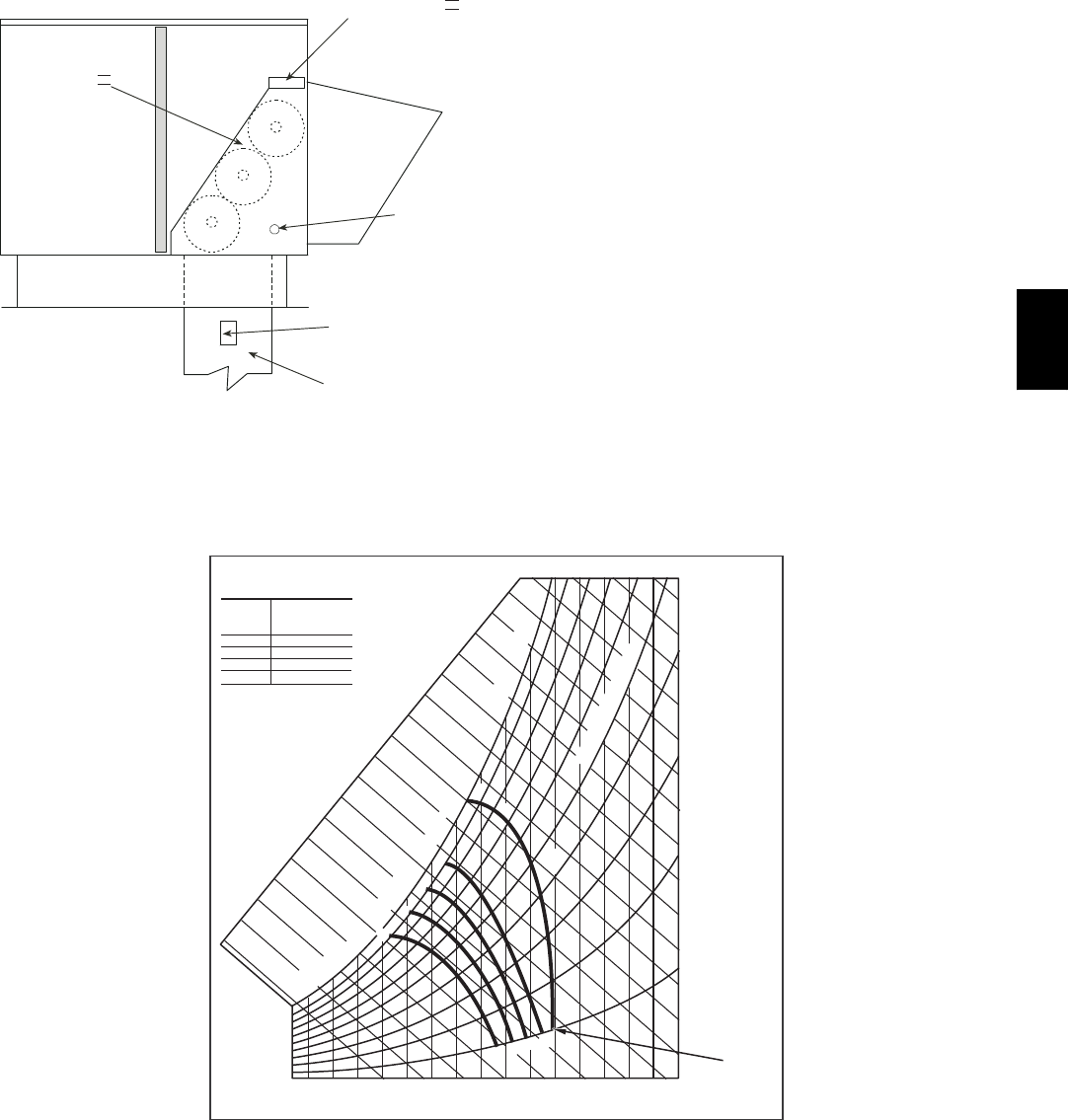
CONTROL
CURVE
A
B
C
D
CONTROL POINT
APPROX.
deg. F (deg. C)
AT 50% RH
73 (23)
70 (21)
67 (19)
63 (17)
1
2
1
4
1
6
1
8
2
0
2
2
2
4
26
28
30
32
3
4
3
6
3
8
40
42
4
4
46
9
0
1
0
0
80
70
6
0
50
4
0
30
20
1
0
ENTHALPY BTU PER POUND DRY AIR
85
(29)
90
(32)
95
(35)
100
(38)
105
(41)
110
(43)
35
(2)
35
(2)
40
(4)
40
(4)
105
(41)
110
(43)
45
(7)
45
(7)
50
(10)
50
(10)
55
(13)
55
(13)
60
(16)
60
(16)
65
(18)
65
(18)
70
(21)
70
(21)
75
(24)
75
(24)
80
(27)
80
(27)
85
(29)
90
(32)
95
(35)
100
(38)
A
A
B
B
C
C
D
D
RELATIVE HUMIDITY (%)
HIGH LIMIT
CURVE
APPROXIMATE DRY BULB TEMPERATURE--degrees F (degrees C)
C06037
Fig. 80 -- Enthalpy Changeover Setpoints
48TC