31
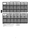
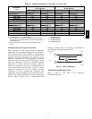
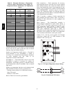
Table 12 – Altitude Compensation* (A04--A06) -- Low NO
x
Units
ELEVA TI ON
ft (m)
60,000, 90,000
BTUH Nominal
120,000
BTUH Nominal
NG Orifice Size LP Orifice Size NG Orifice Size LP Orifice Size
0 --- 2000 (610) 38
2
53
4
32
1
50
3
2000 (610) 39
2
54
4
33
1
51
4
3000 (914) †40 54
4
34
1
51
4
4000 (1219) †41 54
4
35
1
51
4
5000 (1524) †41 54
4
35
1
51
4
6000 (1829) †42 54
4
36
1
52
4
7000 (2134) †42 54
4
36
1
52
4
8000 (2438) †43 55
4
37
2
52
4
9000 (2743) †43 55
4
38
2
53
4
10000 (3048) 44
2
55
4
†40 53
4
11000 (3353) 44
2
55
4
†41 53
4
12000 (3658) 45
2
†56 †42 54
4
13000 (3962) 47
3
†56 †43 54
4
14000 (4267) 48
3
†56 †43 55
4
LEGEND
NG = Natural Gas LP = Liquid Propane
* As the height above sea level increases, there is less oxygen
per cubic ft. of air. Therefore, heat input rate should be reduced
at higher altitudes.
{ Not included in kit. May be purchased separately through
dealer.
1 = CRLPELEV001A00
2 = CRLPELEV002A00
3 = CRLPELEV003A00
4 = CRLPELEV004A00
Minimum heating entering air temperature
When operating on first stage heating, the minimum
temperature of air entering the dimpled heat exchanger is
50_F continuous and 45_F intermittent for standard heat
exchangers and 40_F continuous and 35_F intermittent for
stainless steel heat exchangers. To operate at lower
mixed--air temperatures, a field--supplied outdoor--air
thermostat must be used to initiate both stages of heat
when the temperature is below the minimum required
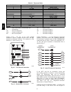
temperature to ensure full fire operation. Wire the
outdoor--air thermostat OALT (part no. HH22AG106) in
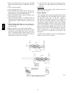
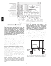
series with the second stage gas valve. See Fig. 39. Set the
outdoor--air thermostat at 35_F for stainless steel heat
exchangers or 45_F for standard heat exchangers. This
temperature setting will bring on the second stage of heat
whenever the ambient temperature is below the thermostat
setpoint. Indoor comfort may be compromised when
heating is initiated using low entering air temperatures
with insufficient heating temperature rise.
LCTB
W2
Thermostat
TH1
TH2
W1
W1
W2
OALT
C08442
Fig. 39 -- OATL Connecti o ns
Troubleshooting Heating System
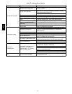
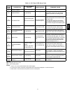
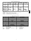
Refer to Table 13 and Table 14 for additional
troubleshooting topics.
48TC


