


41
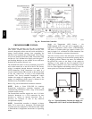
unit shutdown through its NC contact set connected to the
unit’s LCTB input. The FSD function is initiated via the
smoke detector’s Alarm NO contact set. The PremierLink
communicates the smoke detector’s tripped status to the
CCN building control. See Fig. 23 for unit smoke detector
wiring.
Alarm state is reset when the smoke detector alarm
condition is cleared and reset at the smoke detector in the
unit.
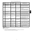
Filter Status Switch — This function is available only
when PremierLink is configured for (Space) Sensor Mode.
PremierLink control can monitor return filter status in two
ways: By monitoring a field--supplied/installed filter
pressure switch or via supply fan runtime hours.
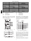
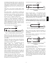
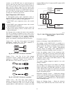
Using switch input: Install the dirty filter pressure switch
according to switch manufacturer’s instructions, to
measure pressure drop across the unit’s return filters.
Connect one side of the switch’s NO contact set to
LCTB’s THERMOSTAT--R terminal. Connect the other
side of the NO contact set to TB1--10. Setpoint for Dirty
Filter is set at the switch. See Fig. 54.
R
10
TB1
LCTB
Thermostat
J4-4
PL
Filter Switch (NO, close on rising pressure (high drop))
C08216
Fig. 54 -- PremierLink Filter Switch Connection
When the filter switch’s NO contact set closes as filter
pressure drop increases (indicating dirt--laden filters), the
input signal to PremierLink causes the filter status point to
read “DIRTY”.
Using Filter Timer Hours: Refer to Form 33CS--58SI for
instructions on using the PremierLink Configuration
screens and on unit alarm sequence.
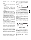
Supply Fan Status Switch — The PremierLink control can
monitor supply fan operation through a
field--supplied/installed differential pressure switch. This
sequence will prevent (or interrupt) operation of unit
cooling, heating and economizer functions until the
pressure switch contacts are closed indicating proper
supply fan operation.
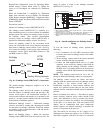
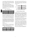
Install the differential pressure switch in the supply fan
section according to switch manufacturer’s instructions.
Arrange the switch contact to be open on no flow and to
close as pressure rises indicating fan operation.
Connect one side of the switch’s NO contact set to
LCTB’s THERMOSTAT--R terminal. Connect the other
side of the NO contact set to TB1--8. Setpoint for Supply
Fan Status is set at the switch. See Fig. 55.
R
8
TB1
LCTB
Thermostat
J4-6
PL
Fan (Pressure) Switch (NO, close on rise in pressure)
C08118
Fig. 55 -- PremierLink Wiring Fan Pressure Switch
Connection
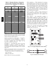
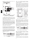
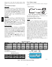
Remote Occupied Switch — The PremierLink control
permits a remote timeclock to override the control’s
on--board occupancy schedule and place the unit into
Occupied mode. This function may also provide a “Door
Switch” time delay function that will terminate cooling
and heating functions after a 2--20 minute delay.
Connect one side of the NO contact set on the timeclock
to LCTB’s THERMOSTAT--R terminal. Connect the other
side of the timeclock contact to the unit’s TB1--2 terminal.
J4-12
R
2
TB1
LCTB
Thermostat
PL
Time Clock
Remote Occupied
C08214
Fig. 56 -- PremierLink Wiring Remote Occupied
Refer to Form 33CS--58SI for additional information on
configuring the PremierLink control for Door Switch
timer function.
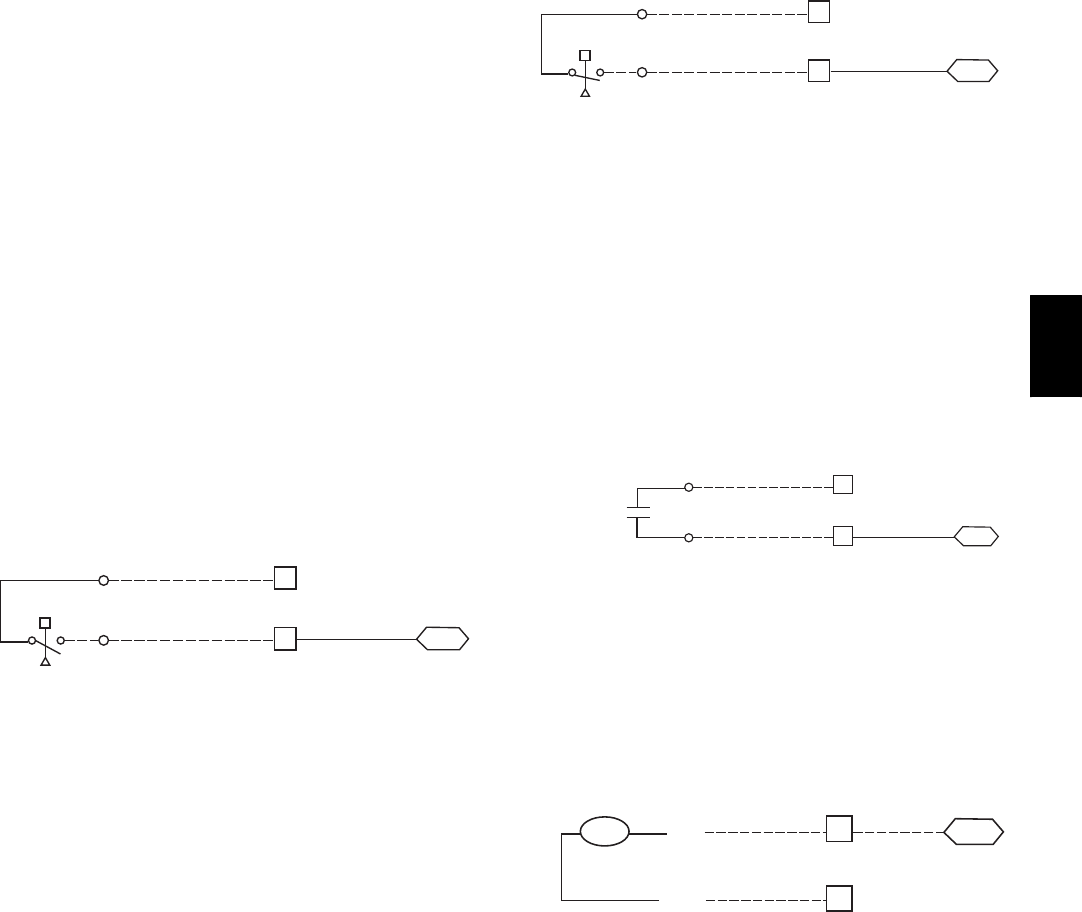
Power Exhaust (output) -- Connect the accessory Power
Exhaust contactor coils(s) per Fig. 57.
Power Exhaust
J8-3
15
C
TB1
THERMOSTAT
PL
PEC
TAN
GRA
LCTB
C08120
Fig. 57 -- PremierLink Power Exhaust Output
Connection
Space Relative Humidity Sensor — The RH sensor is not
used with 48TC models at this time.
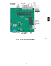
CCN Communication Bus — The PremierLink controller
connects to the bus in a daisy chain arrangement.
Negative pins on each component must be connected to
respective negative pins, and likewise, positive pins on
each component must be connected to respective positive
pins. The controller signal pins must be wired to the signal
ground pins. Wiring connections for CCN must be made
at the 3--pin plug.
48TC