


40
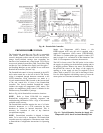
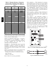
requirements and terminal locations. See Fig. 50 for
typical CO
2
sensor wiring schematic.
8
7
6
5
4
32
1
2
1
HG
24 VAC
OR
24 VDC
NC
ALARM
RELAY
CONTACTS
COM
NO
}
0-10VDC
SIG COM (J4-6)
4-20mA (J4-5)
+
+
-
+
-
C07134
Fig. 50 -- Indoor/Outdoor Air Quality (CO
2
)Sensor
(33ZCSENCO2) -- Typical Wiring Diagram
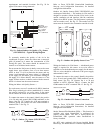
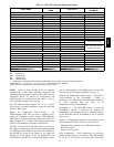
To accurately monitor the quality of the air in the
conditioned air space, locate the sensor near a return--air
grille (if present) so it senses the concentration of CO
2
leaving the space. The sensor should be mounted in a
location to avoid direct breath contact.
Do not mount the IAQ sensor in drafty areas such as near
supply ducts, open windows, fans, or over heat sources.
Allow at least 3 ft (0.9 m) between the sensor and any
corner. Avoid mounting the sensor where it is influenced
by the supply air; the sensor gives inaccurate readings if
the supply air is blown directly onto the sensor or if the
supply air does not have a chance to mix with the room air
before it is drawn into the return airstream.
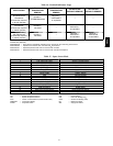
Wiring the Indoor Air Quality Sensor —
For each sensor, use two 2--conductor 18 AWG (American
Wire Gage) twisted--pair cables (unshielded) to connect
the separate isolated 24 vac power source to the sensor
and to connect the sensor to the control board terminals.
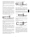
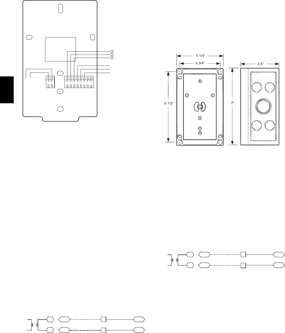
To connect the sensor to the control, identify the positive
(4 to 20 mA) and ground (SIG COM) terminals on the
sensor. See Fig. 50. Connect the 4--20 mA terminal to
terminal TB1--9 and connect the SIG COM terminal to
terminal TB1--7. See Fig. 51.
SEN J5-5
J5-6
COM
9
7
TB1
TB1
IAQ Sensor
PL
24 VAC
C08274
Fig. 51 -- Indoor CO
2
Sensor (33ZCSENCO2)
Connections
Refer to Form 33CS--58SI, PremierLink Installation,
Start--up, and Configuration Instructions, for detailed
configuration information
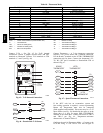
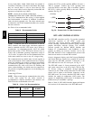
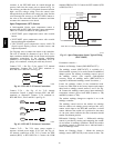
Outdoor Air Quality Sensor (PNO 33ZCSENCO2 plus
weatherproof enclosure) — The outdoor air CO
2
sensor is
designed to monitor carbon dioxide (CO
2
) levels in the
outside ventilation air and interface with the ventilation
damper in an HVAC system. The OAQ sensor is packaged
with an outdoor cover. See Fig. 52. The outdoor air CO
2
sensor must be located in the economizer outside air hood.
COVER REMOVED SIDE VIEW
C07135
Fig. 52 -- Outdoor Air Quality Sensor Cover
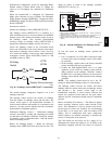
Wiring the Outdoor Air CO
2
Sensor — A dedicated power
supply is required for this sensor. A two--wire cable is
required to wire the dedicated power supply for the sensor.
The two wires should be connected to the power supply
and terminals 1 and 2.
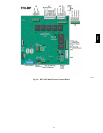
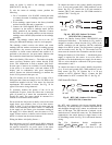
To connect the sensor to the control, identify the positive
(4 to 20 mA) and ground (SIG COM) terminals on the
OAQ sensor. See Fig. 50. Connect the 4 to 20 mA
terminal to 48TC’s terminal TB1--11. Connect the SIG
COM terminal to 48TC’s terminal TB1--13. See Fig. 53.
SEN J5-2
J5-3
COM
13
11
TB1
TB1
PL
OAQ Sensor/RH Sensor
24 VAC
C08275
Fig. 53 -- Outdoor CO
2
Sensor Connections
Refer to Form 33CS--58SI, PremierLink Installation,
Start--up, and Configuration Instructions, for detailed
configuration information.
Smoke Detector/Fire Shutdown (FSD) — This function is
available only when PremierLink is configured for
(Space) Sensor Mode. The unit is factory--wired for
PremierLink FSD operation when PremierLink is
factory--installed.
On 48TC units equipped with factory--installed Smoke
Detector(s), the smoke detector controller implements the
48TC