


16
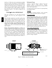
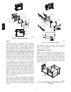
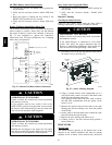
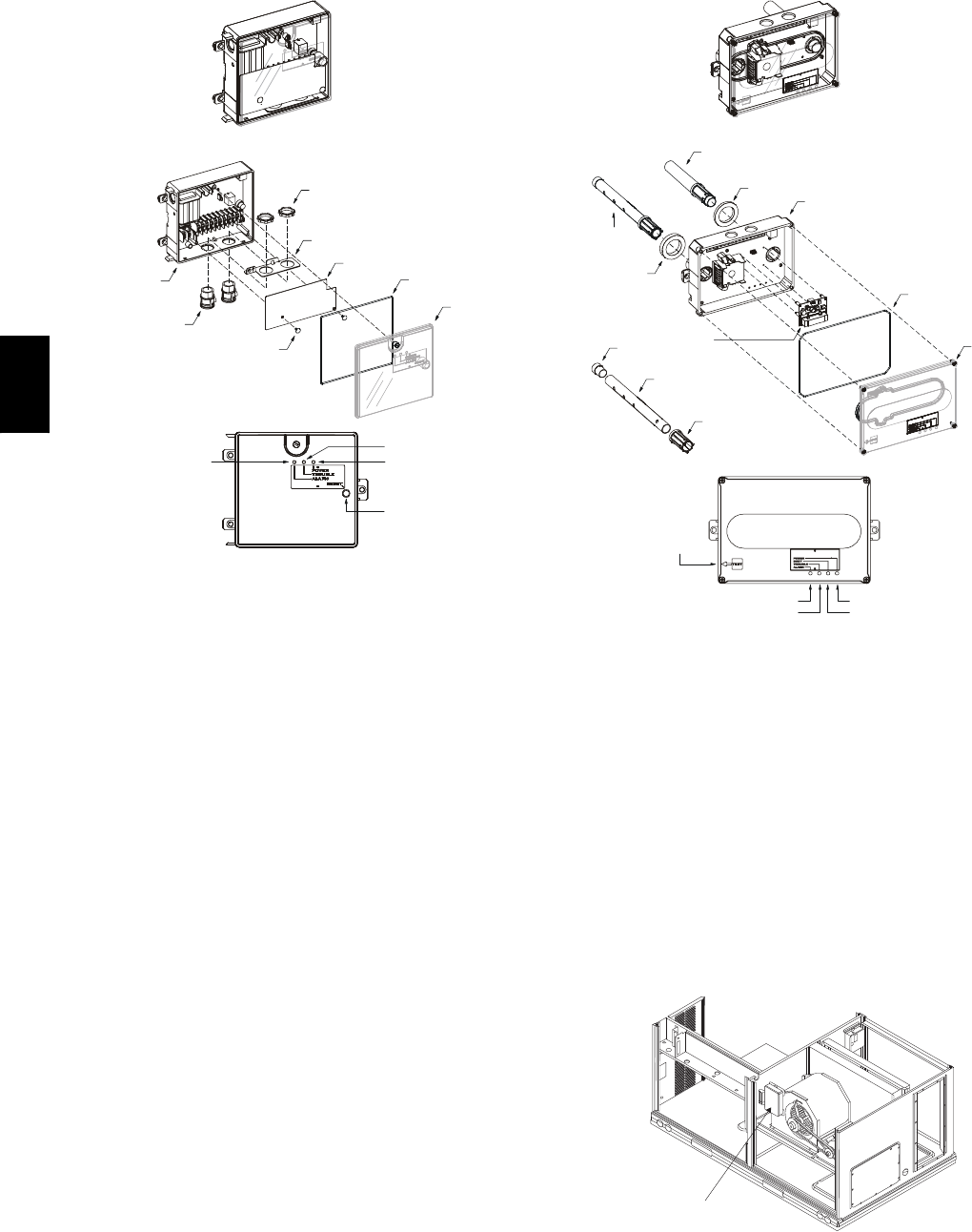
Duct smoke sensor
controller
Fastener
(2X)
Controller cover
Conduit nuts
(supplied by installer)
Conduit support plate
Cover gasket
(ordering option)
Conduit couplings
(supplied by installer)
Terminal block cover
Controller housing
and electronics
Alarm
Power
Te s t / r e s e t
switch
Trouble
C08208
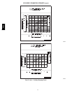
Fig. 16 -- Controller Assembly
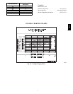
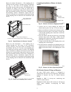
Sensor
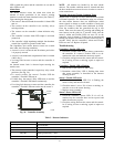
The sensor (see Fig. 17) includes a plastic housing, a
printed circuit board, a clear plastic cover, a sampling
tube inlet and an exhaust tube. The sampling tube (when
used) and exhaust tube are attached during installation.
The sampling tube varies in length depending on the size
of the rooftop unit. The clear plastic cover permits visual
inspections without having to disassemble the sensor. The
cover attaches to the sensor housing using four captive
screws and forms an airtight chamber around the sensing
electronics. Each sensor includes a harness with an RJ45
terminal for connecting to the controller. Each sensor has
four LEDs (for Power, Trouble, Alarm and Dirty) and a
manual test/reset button (on the left--side of the housing).
Air is introduced to the duct smoke detector sensor’s
sensing chamber through a sampling tube that extends into
the HVAC duct and is directed back into the ventilation
system through a (shorter) exhaust tube. The difference in
air pressure between the two tubes pulls the sampled air
through the sensing chamber. When a sufficient amount of
smoke is detected in the sensing chamber, the sensor
signals an alarm state and the controller automatically
takes the appropriate action to shut down fans and
blowers, change over air handling systems, notify the fire
alarm control panel, etc.
The sensor uses a process called differential sensing to
prevent gradual environmental changes from triggering
false alarms. A rapid change in environmental conditions,
such as smoke from a fire, causes the sensor to signal an
alarm state but dust and debris accumulated over time
does not.
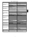
Duct smoke sensor
See
Detail A
Exhaust tube
Plug
Sampling tube
(ordered separately)
Intake
gasket
Cover gasket
(ordering option)
TSD-CO2
(ordering option)
Sensor housing
and electronics
Exhaust gasket
Coupling
Sensor cover
Detail A
Magnetic
test/reset
switch
Alarm
Troub le
Power
Dirty
C08209
Fig. 17 -- Smoke Detector Sensor
For installations using two sensors, the duct smoke
detector does not differentiate which sensor signals an
alarm or trouble condition.
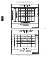
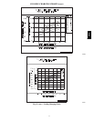
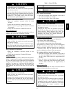
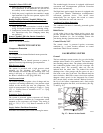
Smoke Detector Locations
Supply Air — The Supply Air smoke detector sensor is
located to the left of the unit’s indoor (supply) fan. See
Fig. 18. Access is through the fan access panel. There is
no sampling tube used at this location. The sampling tube
inlet extends through the side plate of the fan housing
(into a high pressure area). The controller is located on a
bracket to the right of the return filter, accessed through
the lift--off filter panel.
Smoke Detector Sensor
C08245
Fig. 18 -- Typical Supply Air Smoke Detector Sensor
Location
48TC