


61
To determine the minimum position setting, perform the
following procedure:
1. Calculate the appropriate mixed air temperature
using the following formula:
(T
Ox
OA
)
+(TR
x
RA
)=T
M
100 100
T
O
= Outdoor-Air Temperature
OA = Percent of Outdoor Air
T
R
= Return-Air Temperature
RA = Percent of Return Air
T
M
= Mixed-Air Temperature
As an example, if local codes require 10% outdoor
air during occupied conditions, outdoor-air
temperature is 60_F, and return-air temperature is
75_F.
(60 x .10) + (75 x .90) = 73.5_F
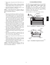
2. Disconnect the supply air sensor from terminals T
and T1.
3. Ensure that the factory-installed jumper is in place
across terminals P and P1. If remote damper
positioning is being used, make sure that the
terminals are wired according to Fig. 59 and that the
minimum position potentiometer is turned fully
clockwise.
4. Connect 24 vac across terminals TR and TR1.
5. Carefully adjust the minimum position
potentiometer until the measured mixed air
temperature matches the calculated value.
6. Reconnect the supply air sensor to terminals T and
T1.
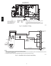
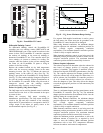
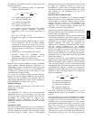
Remote control of the EconoMi$er IV damper is desirable
when requiring additional temporary ventilation. If a
field-supplied remote potentiometer (Honeywell part
number S963B1128) is wired to the EconoMi$er IV
controller, the minimum position of the damper can be
controlled from a remote location.
To control the minimum damper position remotely,
remove the factory-installed jumper on the P and P1
terminals on the EconoMi$er IV controller. Wire the
field-supplied potentiometer to the P and P1 terminals on
the EconoMi$er IV controller. (See Fig. 81.)
Damper Movement
Damper movement from full open to full closed (or vice
versa) takes 2
1
/
2
minutes.
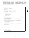
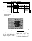
Thermostats
The EconoMi$er IV control works with conventional
thermostats that have a Y1 (cool stage 1), Y2 (cool stage
2), W1 (heat stage 1), W2 (heat stage 2), and G (fan). The
EconoMi$er IV control does not support space
temperature sensors. Connections are made at the
thermostat terminal connection board located in the main
control box.
Occupancy Control
The factory default configuration for the EconoMi$er IV
control is occupied mode. Occupied status is provided by
the black jumper from terminal TR to terminal N. When
unoccupied mode is desired, install a field--supplied
timeclock function in place of the jumper between TR and
N. When the timeclock contacts are closed, the
EconoMi$er IV control will be in occupied mode. When
the timeclock contacts are open (removing the 24--v signal
from terminal N), the EconoMi$er IV will be in
unoccupied mode.
Demand Control Ventilation (DCV)
When using the EconoMi$er IV for demand controlled
ventilation, there are some equipment selection criteria
which should be considered. When selecting the heat
capacity and cool capacity of the equipment, the
maximum ventilation rate must be evaluated for design
conditions. The maximum damper position must be
calculated to provide the desired fresh air.
Typically the maximum ventilation rate will be about 5 to
10% more than the typical cfm required per person, using
normal outside air design criteria.
A proportional anticipatory strategy should be taken with
the following conditions: a zone with a large area, varied
occupancy, and equipment that cannot exceed the required
ventilation rate at design conditions. Exceeding the
required ventilation rate means the equipment can
condition air at a maximum ventilation rate that is greater
than the required ventilation rate for maximum
occupancy. A proportional-anticipatory strategy will cause
the fresh air supplied to increase as the room CO
2
level
increases even though the CO
2
setpoint has not been
reached. By the time the CO
2
level reaches the setpoint,
the damper will be at maximum ventilation and should
maintain the setpoint.
In order to have the CO
2
sensor control the economizer
damper in this manner, first determine the damper voltage
output for minimum or base ventilation. Base ventilation
is the ventilation required to remove contaminants during
unoccupied periods. The following equation may be used
to determine the percent of outside air entering the
building for a given damper position. For best results there
should be at least a 10 degree difference in outside and
return-air temperatures.
(T
Ox
OA
)
+(TR
x
RA
)=T
M
100 100
T
O
= Outdoor-Air Temperature
OA = Percent of Outdoor Air
T
R
= Return-Air Temperature
RA = Percent of Return Air
T
M
= Mixed-Air Temperature
Once base ventilation has been determined, set the
minimum damper position potentiometer to the correct
position.
The same equation can be used to determine the occupied
or maximum ventilation rate to the building. For example,
an output of 3.6 volts to the actuator provides a base
ventilation rate of 5% and an output of 6.7 volts provides
the maximum ventilation rate of 20% (or base plus 15 cfm
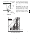
per person). Use Fig. 82 to determine the maximum
setting of the CO
2
sensor. For example, an 1100 ppm
setpoint relates to a 15 cfm per person design. Use the
1100 ppm curve on Fig. 82 to find the point when the CO
2
sensor output will be 6.7 volts. Line up the point on the
48TC