


17
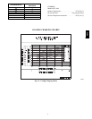
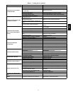
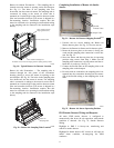
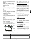
Return Air without Economizer — The sampling tube is
located across the return air opening on the unit basepan.
See Fig. 19. The holes in the sampling tube face
downward, into the return air stream. The sampling tube is
connected via tubing to the return air sensor that is
mounted on a bracket high on the partition between return
filter and controller location. (This sensor is shipped in a
flat--mounting location. Installation requires that this
sensor be relocated to its operating location and the tubing
to the sampling tube be connected. See installation steps
below.)
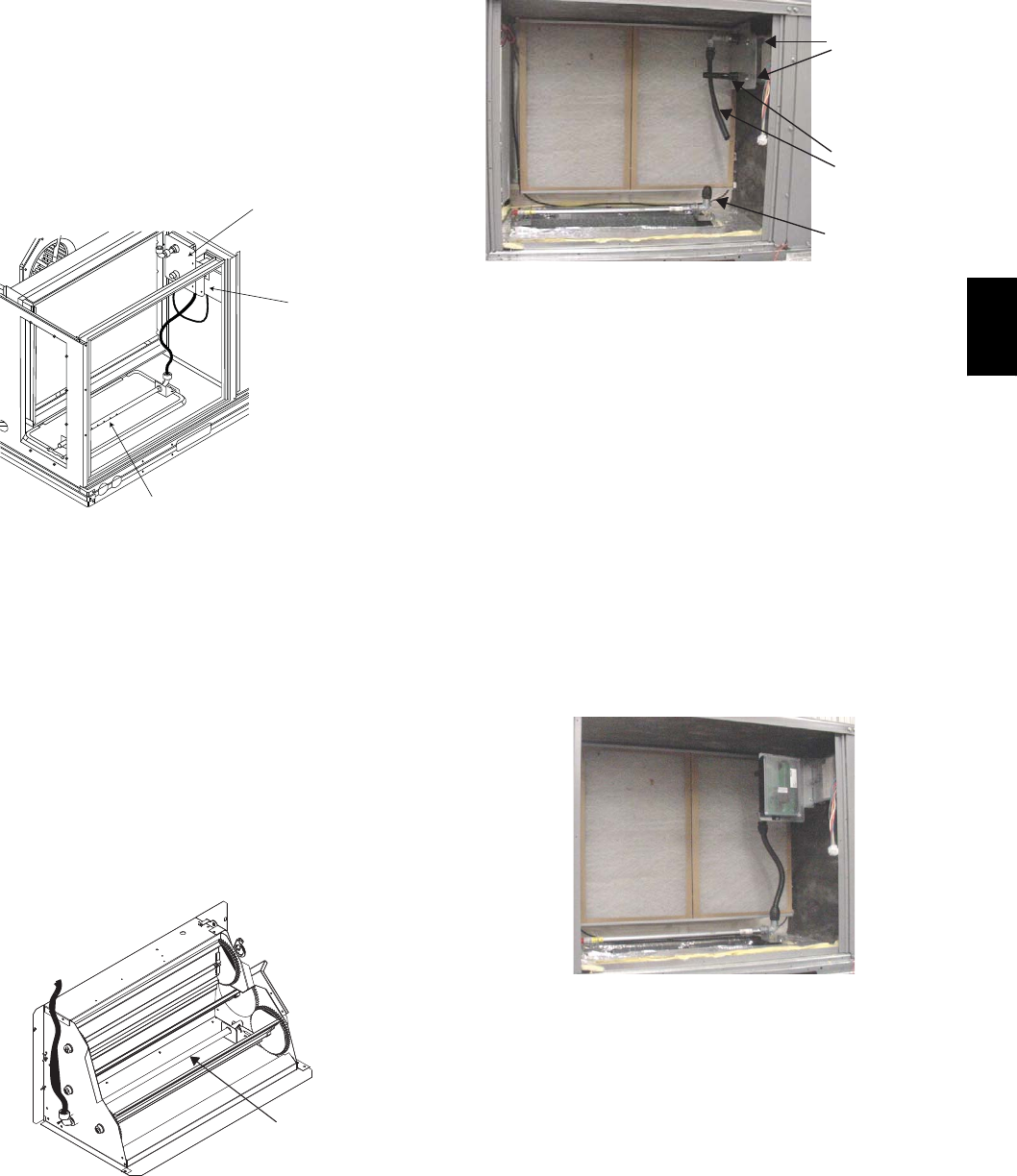
Return Air Detector Sampling Tube
Controller module
Return Air Detector module
(shipping position shown)*
*RA detector must be moved from shipping position to operating position by installer
C07307
Fig. 19 -- Typical Return Air Detector Location
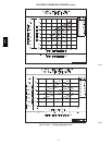
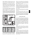
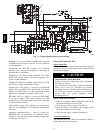
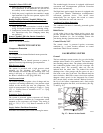
Return Air with Economizer — The sampling tube is
inserted through the side plates of the economizer
housing, placing it across the return air opening on the
unit basepan. See Fig. 20. The holes in the sampling tube
face downward, into the return air stream. The sampling
tube is connected via tubing to the return air sensor that is
mounted on a bracket high on the partition between return
filter and controller location. (This sensor is shipped in a
flat--mounting location. Installation requires that this
sensor be relocated to its operating location and the tubing
to the sampling tube be connected. See installation steps
below.)
Return Air
Sampling Tube
C08129
Fig. 20 -- Return Air Sampling Tube Location
Completing Installation of Return Air Smoke
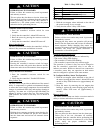
Sensor:
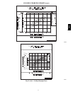
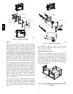
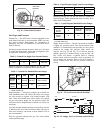
Flexible
Exhaust Tubes
Screws
Sample Tube
C08126
Fig. 21 -- Return Air Detector Shipping Position
1. Unscrew the two screws holding the Return Air
Sensor detector plate. See Fig. 21. Save the screws.
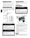
2. Remove the Return Air Sensor and its detector plate.
3. Rotate the detector plate so the sensor is facing out-
wards and the sampling tube connection is on the bot-
tom. See Fig. 22.
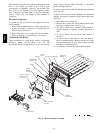
4. Screw the sensor and detector plate into its operating
position using screws from Step 1. Make sure the
sampling tube connection is on the bottom and the ex-
haust tube is on the top. See Fig. 22.
5. Connect the flexible tube on the sampling inlet to the
sampling tube on the basepan.
6. For units with an economizer, the sampling tube is in-
tegrated into the economizer housing but the connec-
tion of the flexible tubing to the sampling tube is the
same.
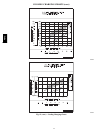
C08127
Fig. 22 -- Return Air Sensor Operating Position
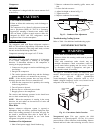
FIOP Smoke Detector Wiring and Response
All units: FIOP smoke detector is configured to
automatically shut down all unit operations when smoke
condition is detected. See Fig. 23, Smoke Detector
Wiring.
Highlight A: JMP 3 is factory--cut, transferring unit
control to smoke detector.
Highlight B: Smoke detector NC contact set will open on
smoke alarm condition, de--energizing the ORN
conductor.
48TC