


45
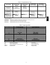
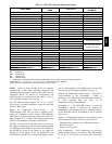
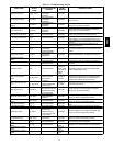
Table 21 – RTU--MP Controller Inputs and Outputs
POINT NAME
BACnet OBJECT
NAME
TYPE OF I/O
CONNECTION PIN
NUMBERS
INPUTS
Space Temperature Sensor sp tsens AI (10K Thermistor) J20 --- 1, 2
Supply Air Temp erature sat AI (10K Thermistor) J 2 --- 1, 2
Local Outside Air Temperature Sensor oatsens AI (10K Thermistor) J 2 --- 3, 4
Space Temperature Offset Pot sptopot AI (100K Potentiometer) J20 --- 3
Indoor Air Quality iaq AI (4 --- 20 ma ) J 4 --- 2, 3
Outdoor Air Quality oaq AI (4 --- 20 ma) J4 --- 5, 6
Safety Chain Feedback safety DI (24 VAC) J1 --- 9
Compressor Safety compstat DI (24 VAC) J 1 --- 2
Fire Shutdown firedown DI (24 VAC) J1 --- 10
Enthalpy Switch enthalpy DI (24 VAC) J2 --- 6, 7
Humidistat Input Status humstat DI (24 VAC) J5 --- 7, 8
CONFIGURABLE INPUTS*
Space Relative Humidity sprh A I (4 --- 20 ma)
J4---2,3 or J4---5,6
Outside Air Relative Humidity oarh AI (4 --- 2 0 m a)
Supply Fan Status fanstat DI ( 2 4 VAC)
J5 --- 1,2 or J 5 --- 3, 4 or
J5 5,6 or J5---7,8
Filter Status filtstat DI (24 VAC)
Remote Occupancy Input remocc DI (24 VAC)
OUTPUTS
Economizer Commanded Position econocmd 4 --- 20ma J2 --- 5
SupplyFanRelayState sf DO Relay (24VAC , 1A) J1 --- 4
Compressor 1 Relay State comp_1 DO Relay (24VAC , 1A) J1 --- 8
Compressor 2 Relay State comp_2 DO Relay (24VAC , 1A) J1 --- 7
Heat Stage 1 Relay State heat_1 DO Relay (24VAC , 1A) J1 --- 6
Heat Stage 2 Relay State heat_2 DO Relay (24VAC , 1A) J1 --- 5
Po wer Exhaust Relay State aux_2 DO Relay (24VAC , 1A) J11 --- 3
Dehumidification Relay State humizer DO Relay (24VAC, 1A) J11 --- 7, 8
LEGEND
AI --- Analog Input
AO --- An alog Ou tput
DI --- Discrete Inpu t
DO --- Discrete Output
* These inputs (if installed) take the place of the default input on the specific channel according to schematic.
Parallel pins J5 --- 1 = J2 --- 6, J5 --- 3 = J1 --- 10, J5 --- 5 = J1 --- 2 are u sed for f ield --- installation.
Refer to the input configuration and accessory sections for more detail.
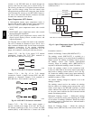
NOTE: Refer to Form 48--50H--T--2T for complete
configuration of RTU--MP, operating sequences and
troubleshooting information. Refer to RTU--MP 3rd Party
Integration Guide for details on configuration and
troubleshooting of connected networks. Have a copy of
these manuals available at unit start--up.
The RTU--MP controller requires the use of a Carrier
space sensor. A standard thermostat cannot be used with
the RTU--MP system.
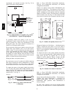
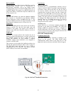
Supply Air Temperature (SAT) Sensor -- On
FIOP--equipped 48TC unit, the unit is supplied with a
supply--air temperature (SAT) sensor (33ZCSENSAT).
This sensor is a tubular probe type, approx 6--inches (12.7
mm) in length. It is a nominal 10--k ohm thermistor. See
Table 15 for temperature--resistance characteristic.
The SAT is factory--wired. The SAT probe is wire--tied to
the supply--air opening (on the horizontal opening end) in
its shipping position. Remove the sensor for installation.
Re--position the sensor in the flange of the supply--air
opening or in the supply air duct (as required by local
codes). Drill or punch a 1/2--in. hole in the flange or duct.
Use two field--supplied, self--drilling screws to secure the
sensor probe in a horizontal orientation. See Fig. 41.
Outdoor Air Temperature (OAT) Sensor -- The OAT is
factory--mounted in the EconoMi$er 2 (FIOP or
accessory). It is a nominal 10k ohm thermistor attached to
an eyelet mounting ring. See Table 15 for
temperature--resistance characteristic.
EconoMi$er 2 -- The RTU--MP control is used with
EconoMi$er2 (option or accessory) for outdoor air
management. The damper position is controlled directly
by the RTU--MP control; EconoMi$er 2 has no internal
logic device.
Outdoor air management functions can be enhanced with
field--installation of these accessory control devices:
Enthalpy control (outdoor air or differential sensors)
Space CO
2
sensor
Outdoor air CO
2
sensor
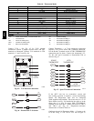
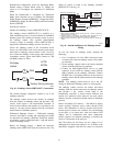
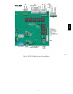
Field Connections -- Field connections for accessory
sensors and input devices are made the RTU--MP, at plugs
J1, J2, J4, J5, J11 and J20. All field control wiring that
48TC