


74
S If the PremierLink controller is in the occupied mode and
ASHRAE 90.1 Supply Fan is configured for Yes when
Linkage is active and the Linkage Coordinator device is
sending an occupied mode flag
S When Temperature Compensated Start is active
S When Free Cool is active
S When Pre--Occupancy Purge is active
S Whenever there is a demand for cooling or heating in the
unoccupied mode
S Whenever the Remote Contact input is configured for
Remote Contact (RC_DC=1 in SERVICE table) and it is
closed or the point is forced Closed via communications
in the STATUS01 points display table (remote contact
closed = occupied, remote contact open = unoccupied)
S Whenever the H3_EX_RV point is configured for
Dehumidification (AUXOUT=5 in CONFIG table) and it
is in the unoccupied mode and the indoor RH exceeds the
unoccupied humidity setpoint
S Whenever the Supply Fan Relay point is forced On in the
STATUS01 points display table
The fan will also continue to run as long as compressors
are on when transitioning from occupied to unoccupied
with the exception of Fire Shutdown mode. If the Fire
Shutdown input point is closed or forced in the
STATUS01 points display table, the fan will be shutdown
immediately regardless of the occupancy state or demand.
The PremierLink controller has an optional Supply Fan
Status input to provide proof of airflow. If this is enabled,
the point will look for a contact closure whenever the
Supply Fan Relay is on. If the input is not enabled, then it
will always be the same state as the Supply Fan Relay.
The cooling, economizer and heating routines will use this
input point for fan status.
Cooling — The compressors are controlled by the Cooling
Control Loop that is used to calculate the desired SAT
needed to satisfy the space. It will compare the SPT to the
Occupied Cool Setpoint (OCSP) + the T56 slider offset
(STO) when occupied and the Unoccupied Cool Setpoint
(UCSP + Unoccupied Cooling Deadband) if unoccupied
to calculate a Cooling Submaster Reference (CCSR) that
is then used by the staging algorithm (Cooling submaster
loop) to calculate the required number of cooling stages.
The economizer, if available, will be used as the first
stage of cooling in addition to the compressors. This loop
runs every minute. The following conditions must be met
in order for this algorithm to run:
S indoor fan has been ON for at least 30 seconds
S heat mode is not active and the time guard between
modes equals zero.
S mode is occupied or the Temperature Compensated Start
or Cool mode is active
S SPT reading is available and > (OCSP + STO)
S If mode is unoccupied and the SPT > (UCSP +
Unoccupied Cooling Deadband). The indoor fan will be
turned on by the staging algorithm.
S OAT > DXLOCK or OAT DX Lockout is disabled
If all of the above conditions are met, the CCSR will be
calculated, otherwise it is set to its maximum value and
DX stages is set to 0. If only the last condition is not true
and an economizer is available, it will be used to cool the
space.
The submaster loop uses the CCSR compared to the actual
SAT to determine the required number of capacity stages
to satisfy the load. There is a programmable minimum
internal time delay of 3 to 5 minutes on and 2 to 5 minutes
off for the compressors to prevent short cycling. There is
also a 3--minute time delay before bringing on the second
stage compressor. If the PremierLink controller is
configured for Heat Pump and AUXOUT is configured for
Reversing Valve Cool, the H3_EX_RV output will
energize 2 seconds after the first compressor is energized
and stay energized until there is a demand for heat. If
AUXOUT is configured for Reversing Valve Heat, then
the H3_EX_RV contact will be deenergized when there is
a demand for cooling. An internal 5 to 10--minute
user--programmable time guard between modes prevents
rapid cycling between modes when used in a single zone
application. The Time Guard is lowered to 3 minutes
when Linkage is active to allow the 3Vt linkage
coordinator to have better control of the PremierLink
controller when used as the air source for the 3V control
system.
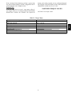
Table 29 indicates the number of stages available. The
staging algorithm looks at the number of stages available
based the number of cool stages configured in the
SERVICE configuration table. The algorithm will skip the
economizer if it is not available and turn on a compressor.
Table 29 – Available Cooling Stages
NUMBER OF
STAGES
0
1
(ECONOMIZER* )
2 3
Compressor 1 Off Off On On
Compressor 2 Off Off Off On
* If conditions are suitable for economizer operation.
Any time the compressors are running, the PremierLink
controller will lockout the compressors if the SAT
becomes too low. These user configurable settings are
found in the SERVICE configuration table:
Compressor 1 Lockout at SAT < SATLO1 (50 to 65_F)
(default is 55_F)
Compressor 2 Lockout at SAT < SATLO2 (45 to 55_F)
(default is 50_F)
After a compressor is locked out, it may be started again
after a normal time--guard period and the supply air
temperature has increased at least 8_F above the lockout
setpoint.
Dehumidification — The PremierLink controller will
provide occupied and unoccupied dehumidification
control when AUXOUT = 5 in the CONFIG table and is
installed on HVAC units that are equipped with additional
controls and accessories to accomplish this function. This
function also requires a space relative humidity sensor be
installed on the OAQ/IRH input.
48TC